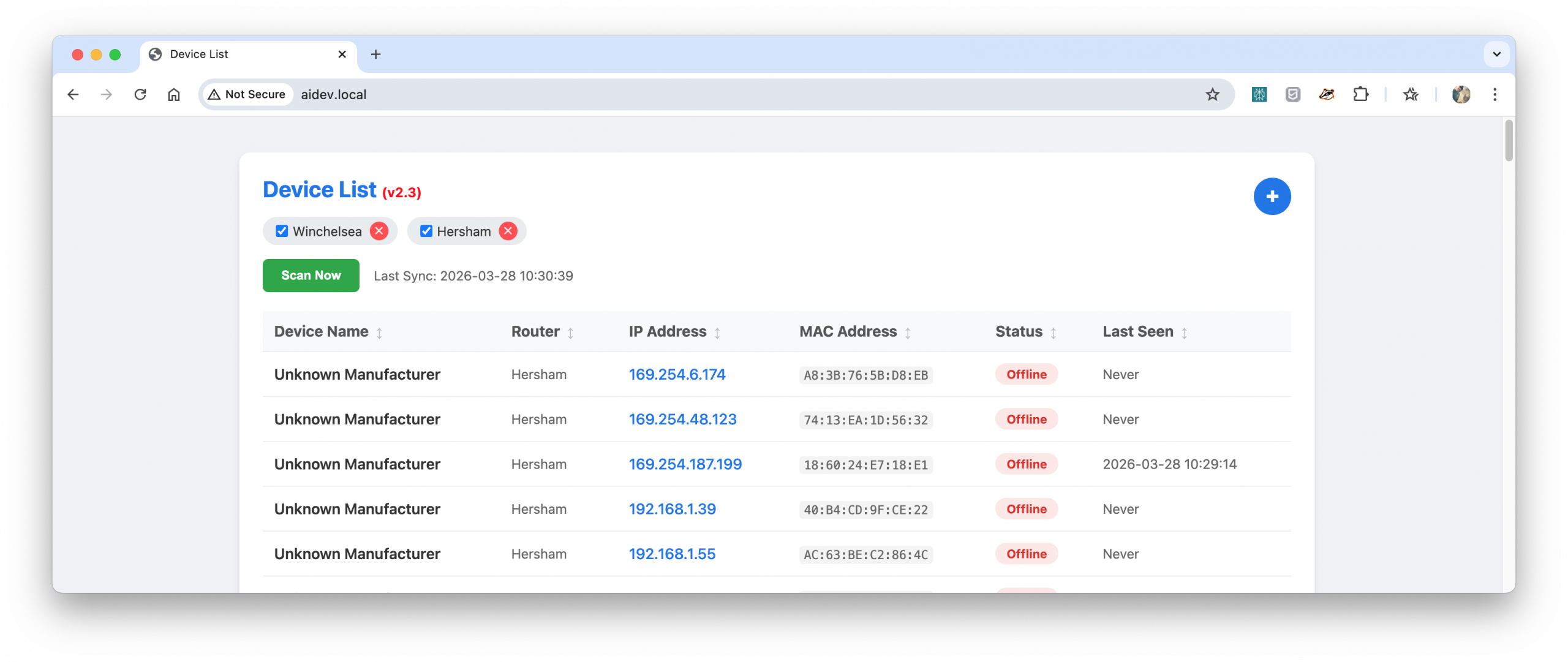
Locating the IP addresses of devices on a local network can be tedious. It usually requires logging into router web interfaces to view DHCP lease tables, where devices are often listed with unhelpful manufacturer default names or simply as “Unknown”.
What
DHCP-Devicelist is a lightweight, Dockerized web application. It connects to your network routers, extracts active DHCP leases, and displays them in a clean, searchable, and sortable web dashboard. The application translates raw MAC addresses into human-readable friendly names.
How
The application relies on several core components to automate this process:
SNMP Polling: A background Python script uses snmpwalk to query the configured routers for their ARP and DHCP tables. This maps active IP addresses to their hardware MAC addresses.
Device Name Translation: A local known_devices.json file maps MAC addresses to user-defined friendly names.
Web Dashboard: A Python Flask server hosts a frontend interface. The UI allows users to sort devices, dynamically add or remove routers to be monitored, and view the network state.
Scheduling: Data refreshes automatically every 24 hours. A “Sync Now” button triggers an immediate on-demand SNMP poll for newly connected devices.
Deployment: The entire application is packaged into a single Docker container, deployable via docker-compose with persistent volumes for user configuration.
Source code and installation instructions are available on GitHub: DHCP-Devicelist.
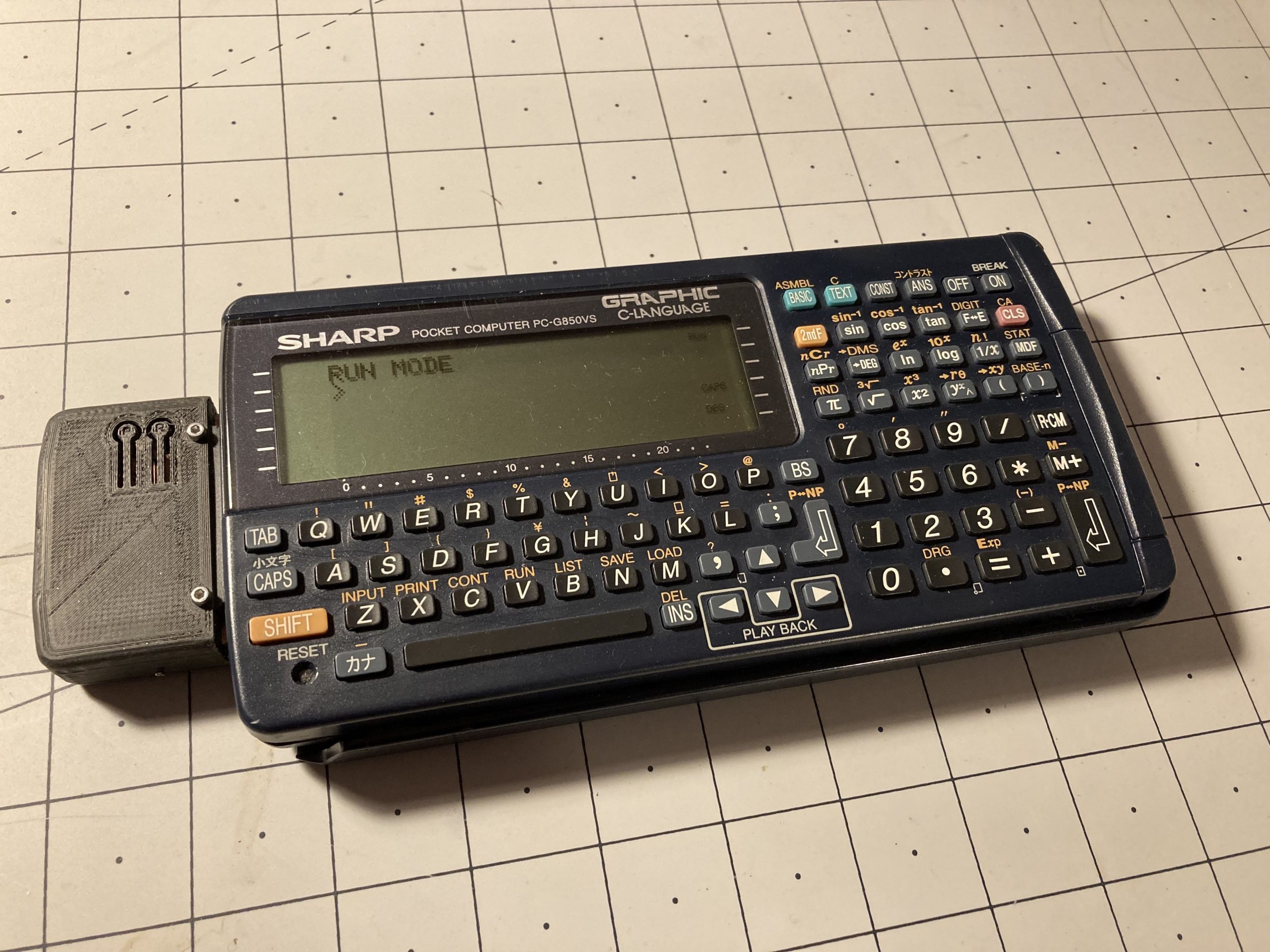
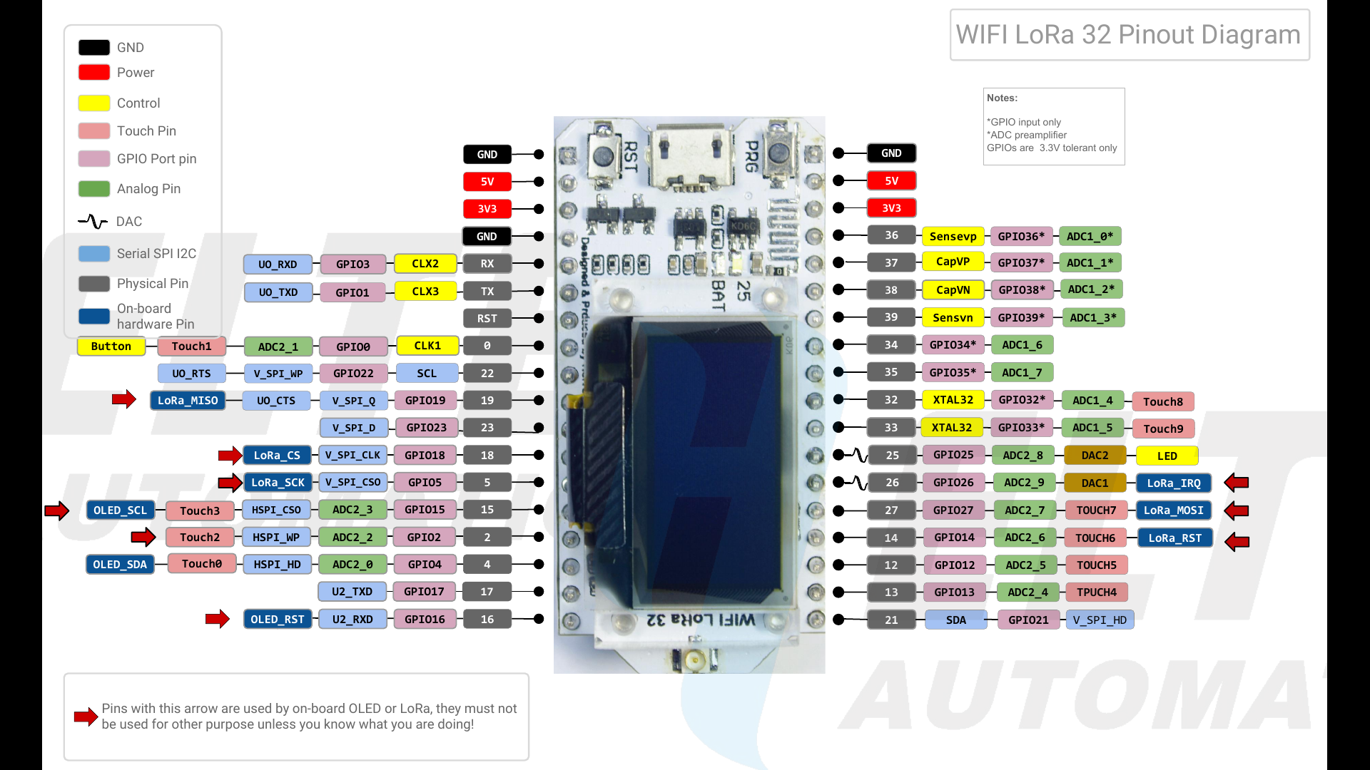
YAEP (Yet Another ESP Powered Project): An ESP8266-12 powered WiFi module for the Sharp Pocket Computer via the 11-pin connector connects wireless to PCs for transfer of programs and data.
The ESP8266 connects to your home WiFi or acts as an AP for initial configuration. The Serial port of the G850 becomes accessible via TCP on port 23. You can use telnet or netcat (nc) for simple direct transfers to/from the PC or use socat to create a virtual com port. The module supports 9600baud and shortens CTS/RTS and pulls these signals up to +5V, so you need to use XON for flow control.
Please note:
The G850 uses inverted serial protocol logic levels (i.e. logical “high” is represented by a “low” (0V) TTL level, logical “low” is represented by a 5V TTL level. The ESP8266 uses the SoftSerial library on GPIO 4 and 5, which supports inverted logic levels
Raw TCP is implemented without encryption on port 23. You can connect via telnet to receive or send data or programs but everyone on the same network can read the transferred data in clear text
The module does only support serial port communication (i.e. it does not emulate the CE-126 synchronous communication for print and cassette tape commands)
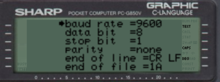
In the TEXT/Sio/Format menu enable 9600 baud, 8N1 and no flow-control. End-of-file “1A” allows the G850 to stop listening when receiving a file. You can still send files without the end-marker, but need to interrupt the “load” command by pressing “ON/BREAK”. The received text will be in the editor.
Sleep timeout can be set. The module starts blinking befor it goes to sleep and pressing the PRG button resets the sleep timout.
Some basic “AT” commands allow configuration changes without having to re-flash the module
Tex/Sio/Format menu
Why not Bluetooth? I started out using a HC-06 BT module, but learned along the way that this module is no longer supported by Windows 10’s BT stack. After several hours of fruitless tests, I gave up and resorted first to an ESP32. However, the BT stack that implements a serial port pushes even the most bare-bone program beyond 1MB in size (thank you Espressif), so I opted for raw TCP instead.
I have not noticed that the WiFi module decreases battery life dramatically, especially since I implemented deep-sleep.
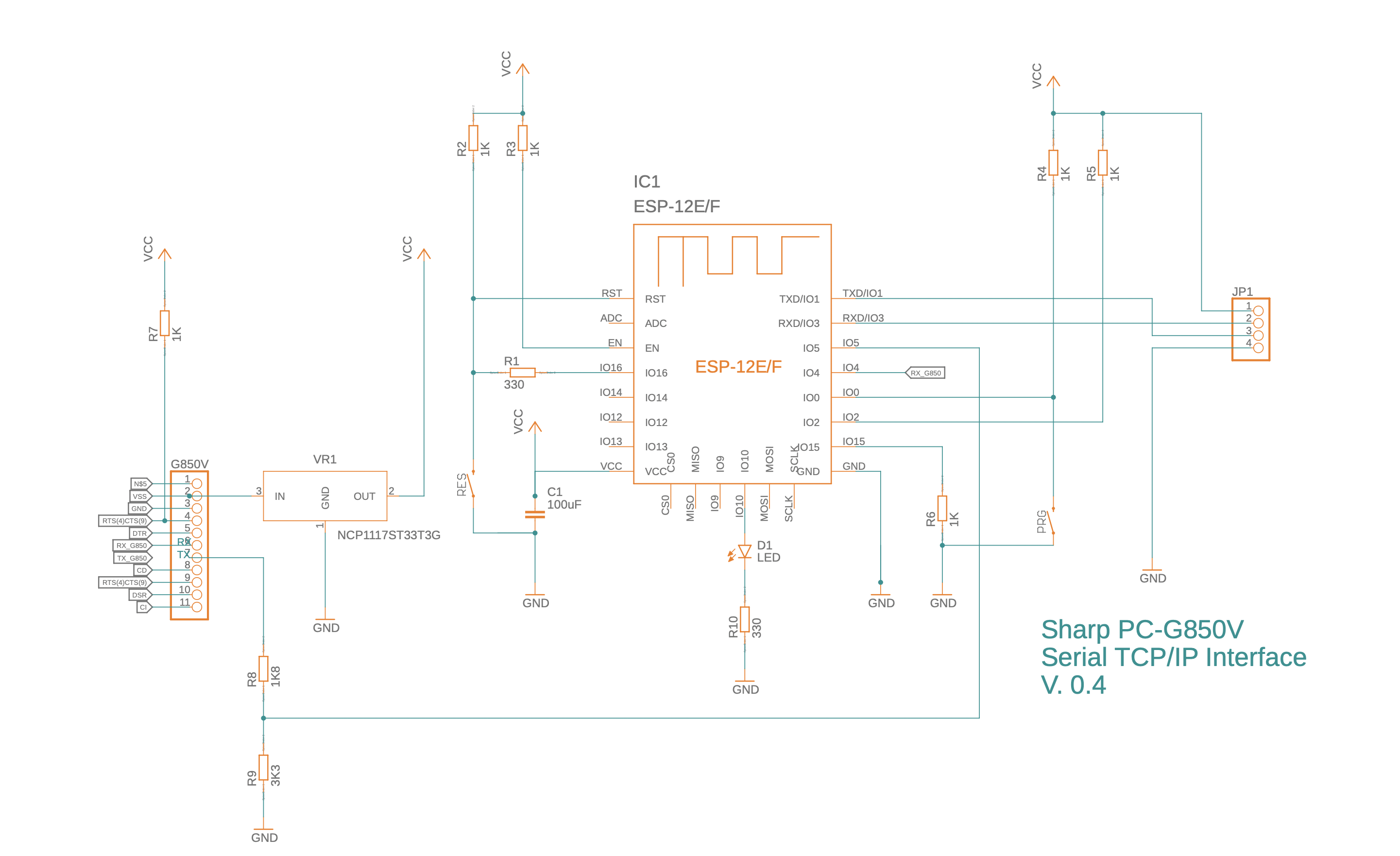
WiFI Serial Module for Sharp PC-G850
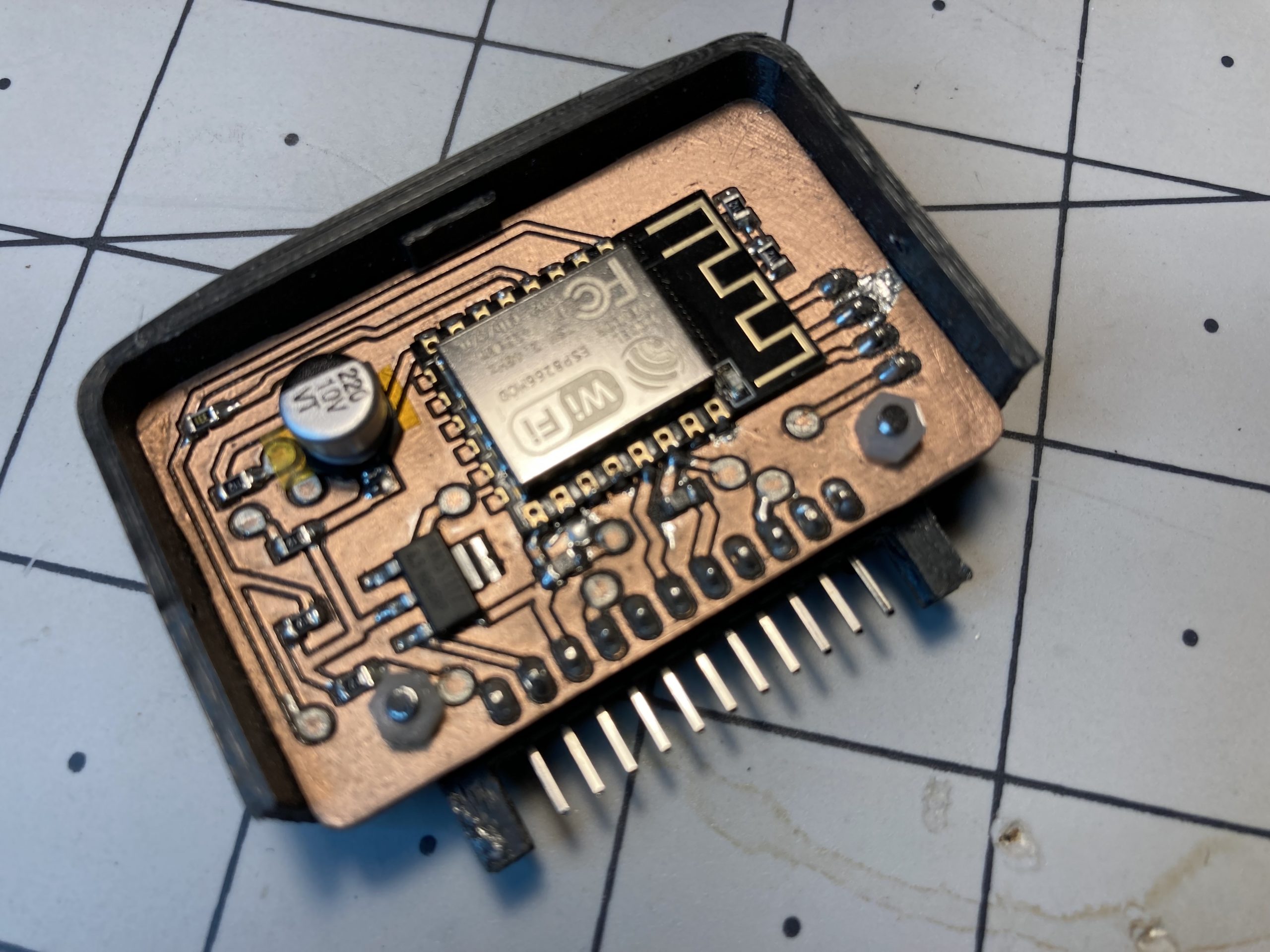
The module is a double sided PCB. I isolation-routed it with FlatCAM. Top-side is very much limited to traces and the two buttons, all vias can be manufactured with just copper wire (i.e. no through-hole rivets required) and all pins only need soldering on the bottom-side. You can find the EAGLE files at the end of this post.
The module consists of a double sided 1.5mm PCB, an ESP8266-12, a 3.3V voltage regulator, a 6x 1K, 2 x 330Ohms, 1 x 1.5K, 1 x 3K3 SMD resistors (0805 type), a 100uF capacitor, 1x LED (0805) and a 90 degree 11-pin header. The G850 connector and the case are 3D printed.
Disclaimer: I am not an electrical engineer. These projects are a way for me to learn and figure out ways to overcome the problems I encounter. By all means, if you have suggestions for doing things better, please let me know.
You can reach me on bsky at @thechrisherman.bsky.social if you need help.
ESP8266 module PCB and 3D printed 11-pin connector (bottom view, version 3)
Schematic, version 4 (.sch file available in resource section)
11-pin connector: A 3D part for the 11-pin connector which others may be able to re-use in their designs. The 2mm drill holes need to be positioned 200mil (5.08mm) above and below the connector and 100mil (2.54mm) in the orthogonal direction, away from the axis formed by the 11 pins (see picture below)
Sending and receiving files
To receive a file, plug-in the module (hostname of my module is G850V.local), type on the PC (OSX/Linux):
nc G850V.local 23>test.c
And on the G850 press TEXT, then S (for Sio) and S again (for Save). Terminate nc with ^c on the PC
To send a file, first press TEXT, S (for Sio) and L (for load) on thje G850. Then type on the PC:
nc G850V.local 23 <test.c
terminate nc with ^c on the PC
AT commands
Baudrate (1200..9600), WiFi settings and sleep timeout can be set via a small set of “+++AT+” commands. These commands can be sent from the G850 or via netcat ot telnet from your PC/Mac (of course, this will require your WiFi settings work). There’s also a “failsafe” configuration that can be selected when pressing the PRG button of the module for 5 sec:
this sets the SSID to “GUEST” and the wifi access point password to “pw”.
numeric configuration items: rev: integer, referencing the version of the configuration. I recommend leaving at 1 sleep: seconds until unit goes into deep sleep baud: baudrate for connection with G850 (600…9600) port: TCP/IP port (use 23 for telnet compatibility)
string configuration items: ssid: the ssid name of your wifi wifipw: password of your wifi network host: hostname for use when requesting an IP address otapw: password for protrcting your ota passwords (use espota protocol)
+++AT+SAVE Returns: OK Saves current configuration as failsafe.ini to LittleFS Flash file system. Pressing the PRG button for longer than 5 sec will load failsafe.ini configuration and reboot. This allows you to recover from a messed-up config.ini (e.g. wrong wifi credentials).
+++AT+SLEEP Returns: OK Puts the adapter immediately into sleep. Pressing the RES button on the module will wake it up.
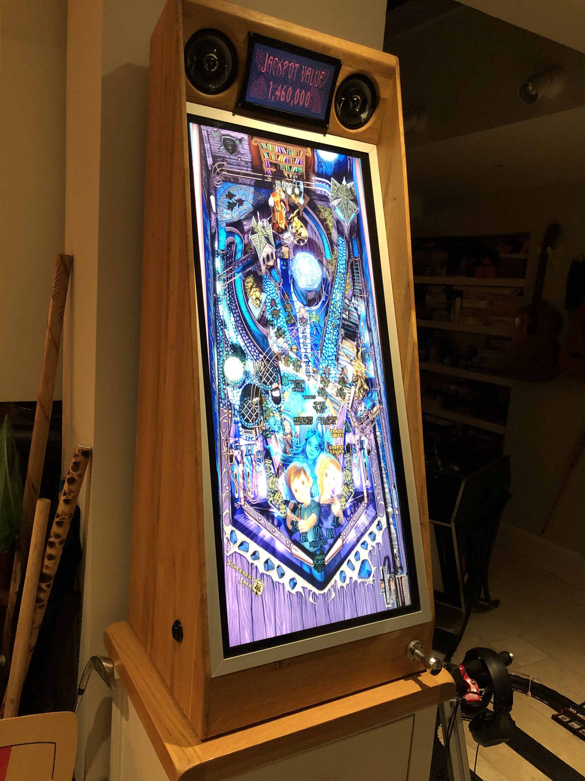
Architecture The vertical Pinball machine was build on a Windows 10, Optiplex 3020 (i5) with 8GB RAM and a 16GB Radeon RX 590 (8 GB GDDR5).
The Dell Optiplex shows a BIOS error when the front cover is not connected (and I threw it away before realizing I should have kept the cable). So I added an additional Arduino that emulates a keyboard and sends an “F2” keystroke 5 seconds after power-up.
I am particular proud of the inductive plunger, which allows skill shots without use of a linear potentiometer (no wear!). You can Google “Arduino Inductance LM339” and will find good description of how to do it. Schematics and board can be found in the resource section.
One problem remains unsolved: I need an external keyboard to shutdown windows. I did not want to mess with any software that maps keystrokes, so at the end of the gaming night, I pull out a little wireless keyboard and shutdown Windows. No enough of an inconvenience to warrant drilling another hole in the cabinet.
Cabinet I ordered a kitchen worktop (2m x 0.9m x 2cm), cut it into 12cm wide boards of 2cm thicknes and various lengths, halved the thickness to about 8mm (thereby doubling the number of boards), glued the boards together to form 8mm thick sheets and cut the sides of the cabinet. Easy. Could have ordered oak boards right away. <LINK TO CABINET>
For the subwoofer and speaker cut-outs I used a laminate cutter (also known as a hand router), with a ball bearing at the tip. I printed jigs with my 3D printer that I screwed to the bottom of the board to guide the router. This produced super neat and perfectly round cutouts.
I used a biscuit jointer when making the large boards. That was a stupid idea because you need to know where you make the cuts and ensure there’s no biscuit where you cut the board: it looks ugly when the biscuit shines through at an edge, like the diagonal cut that I had to make for the front of the cabinet.
Windows PC The Dell Optiplex 3020 was gutted and basically only the mainboard survived, mounted on an open frame at a 20 degree angle. The Dell PSU was replaced with a Corsair VX550 (the Optiplex mainboard requires a PSU adapter cable which can be ordered from Amazon for £10. A cheap 256GB SSD stores the data.
Beware that the Dell motherboard will report an error and not booting unless the frontpanel is attached. I learned the hard way AFTER I had thrown away the Dell case and NOT retained the front panel or cable. So I programmed an Arduino to simulate an “F2” keypress shortly after boot to get past the error message.
The mainboard is mounted at an angle on a simple frame.
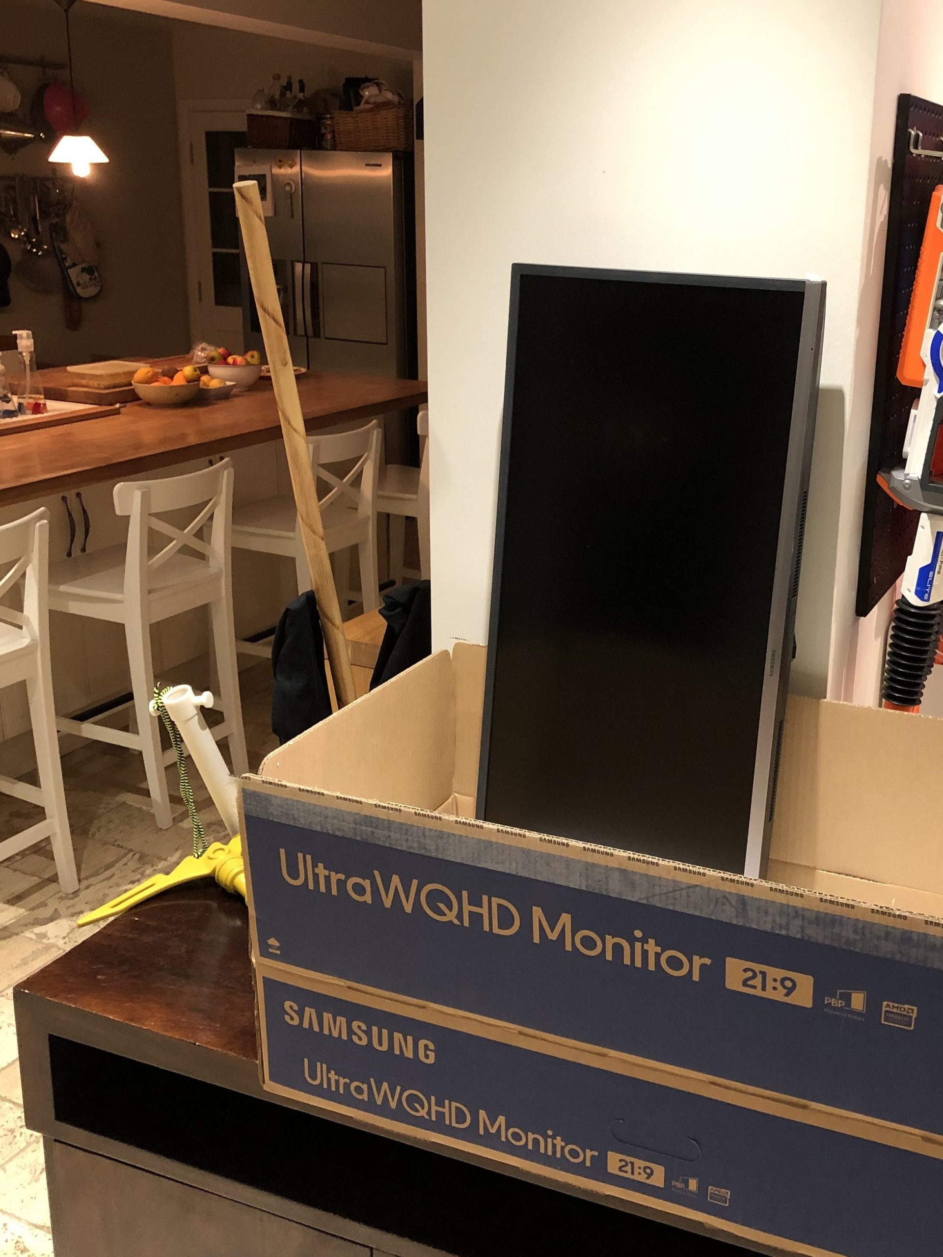
Screens A Samsung LS34J550WQUXEN 34″ Ultra Wide LED Monitor (WQHD 3440×1440, Freesync, 2 x HDMI, DisplayPort) was dissected (use a credit card to buy it and then later to pry the case open. Comes apart very neatly.
I build a pine frame that the monitor rests on, with an 5mm tempered glass pane on top. Black spray paint from the back creates a nice bezel that covers the edge of the display and the wooden frame. Everything is held in place by 20x30mm aluminium profiles (I screwed up and cut one side 1mm too short, so had to patch it. not my proudest moment, but I ran out of profile and then lockdown hit and I couldn’t get to the hardware store).
The small top screen is a super cheap AliExpress 1024×600 screen. A small OLED display would have been better I suspect, because I went a bit too cheap on the smalls screen and as a result it’s not quite as bright as I would have liked it to be.
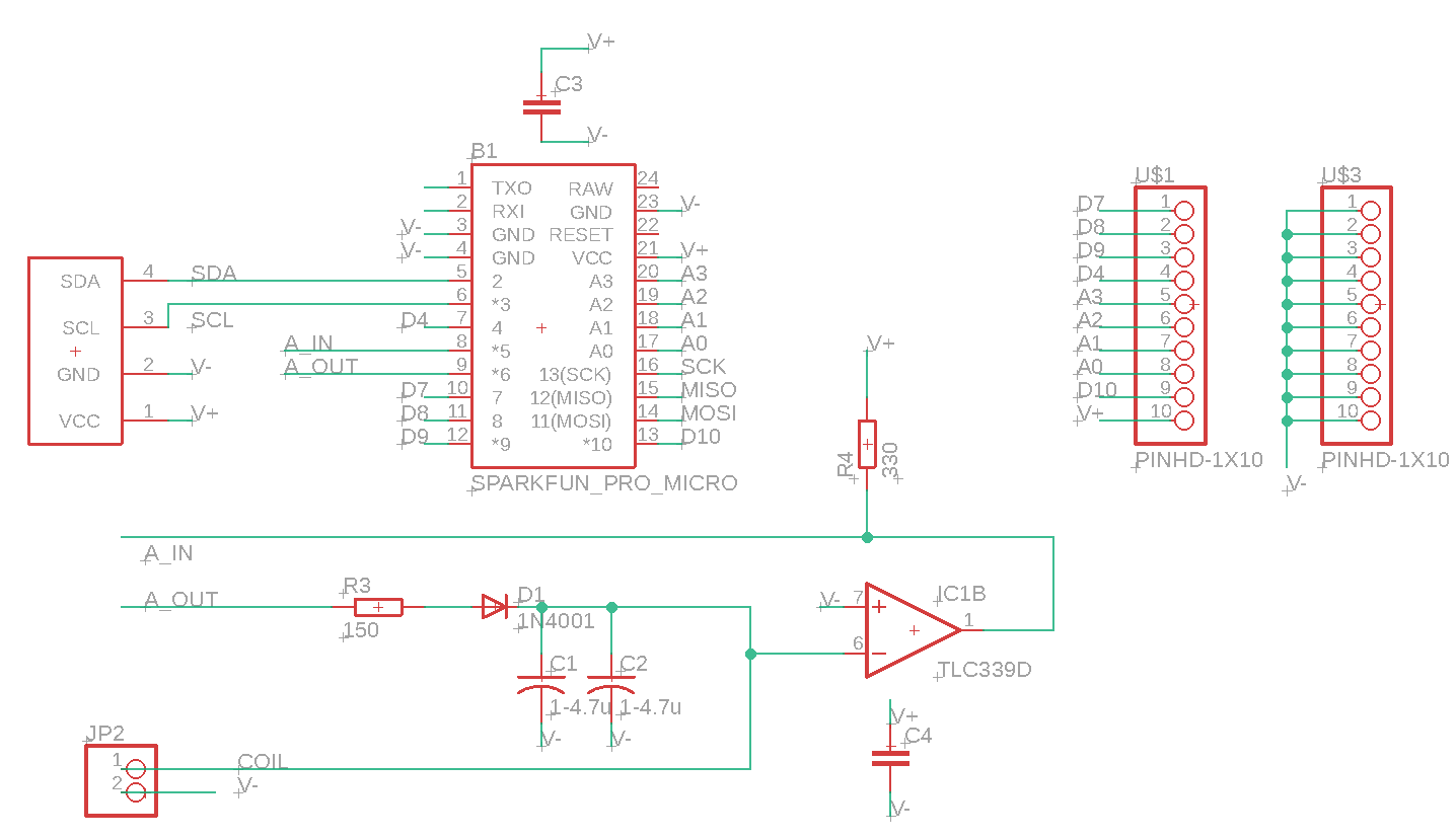
Buttons and Plunger/Inductance Meter Figuring out how to measure the position of the plunger with a coil took the longest. Usually you either trigger a switch or pull a linear potentiometer back and forth. The latter allows trick shots.
I did not like the idea to attach a potentiometer to the plunger and having to deal with the mechanical hassle, potentially incurring problems after hours of use (the plunger is difficult to reach and not easily removable.
The idea was to wind a coil around the plunger and as the plunger retracts, it pulls out of the coil which should change the magnetic flow and the inductance of the coil.
There are great guides out there that describe how to use an Arduino to measure inductance. So I thought how hard can it be?
The circuit works as follows:
The Arduino triggers a pulse that “rings the bell”. The bell in this case is the coil and a capacitor.
Coil and capacitor form an LC oscillator. The frequency depends on the capacitance and the inductance. If you keep the capacitor (1uF) fixed, then the change in frequency is an indication for the change in inductance, which in turn is an indication of how far the plunger is pulled out of the coil.
Using an LM339 helps converting the analog signal into a TTL signal that the Arduino can measure. The length of a pulse is a measure for the position of the plunger. See it in action here:
Schematic:
The Arduino simulates a joystick and sends the position of the plunger as z-axis values to the PC. It also takes care of the buttons that control the flippers, the gamepad, Select, Start and Back. The Atmega 32U4 has a build-in USB controller (you cannot use an Arduino Uno because it relies on an external USB-Serial controller).
Was it worth it? Was it worth it? Many people on the Internet will tell you that virtual pinball machines are inferior, but I disagree. While virtual tables can’t match the tactile feedback and nostalgia of a real pinball machine, they should be viewed as a unique category. Is it the same as a “real” pinball machine? Absolutely not—it’s essentially a vertical screen. However, the experience is highly engaging, and the FX3 software is impressively realistic. The reduced space requirements, combined with the flexibility to play any pinball machine I want and the ability to own dozens of different tables in one package, make it worthwhile.
I enjoyed the building process and figuring out how to make the inductive plunger work. Even after about eight months, playing my vertical pinball machine remains fun, and it’s exciting to see new tables being released each month.
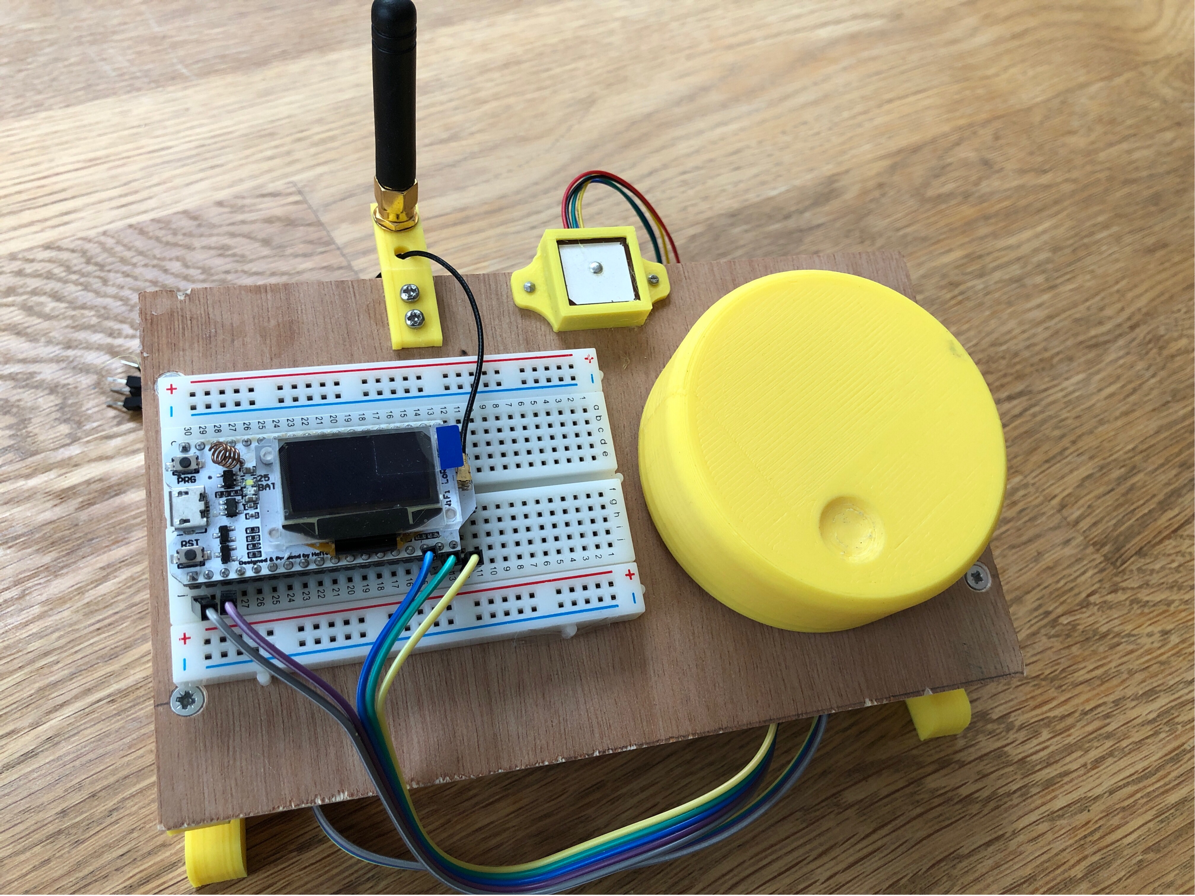
A few months ago, I installed a LoRa Gateway and I was able to talk a friend into setting up a second gateway. Both are connected the TheThingsNetwork.org.
The idea is to build cheap, simple sensors for all sorts of stuff (temperature, rain, wind, usage of the football goals) and place them around our village (garden, school, commons, etc.).
The problem
But we do not know the range of our gateways just yet. Of course, we could get in our car with a simple module and drive until we lose connectivity. But where is the fun in that?
So the plan is to build a GPS enabled LoRa module, that logs the signal strength and allows us to draw a heat map of LoRa coverage in our area. It should also allow us to test different antennas and understand better how they influence the range.
The solution
An ESP32 with LoRa and display was sitting in my drawer and I ordered a GPS/GLONASS module from AliExpress. Everything us assembled on an impromptu test rack, ready to e powered by a USB power bank.
(The big yellow knob is a rotary encoder)
Next Steps:
Get the GPS to work (fuGPS library)
Get the display to work (U8g2lib library)
Connect the rotary encoder
Implement a menu system for parameter editing and control (ArduinoMenu library)
Figure out how to derive meaningful signal strength data from the LoRa transceiver
Connect an SD Card reader and log GPS and LoRa data
Do some wardriving and create a heat map of the area
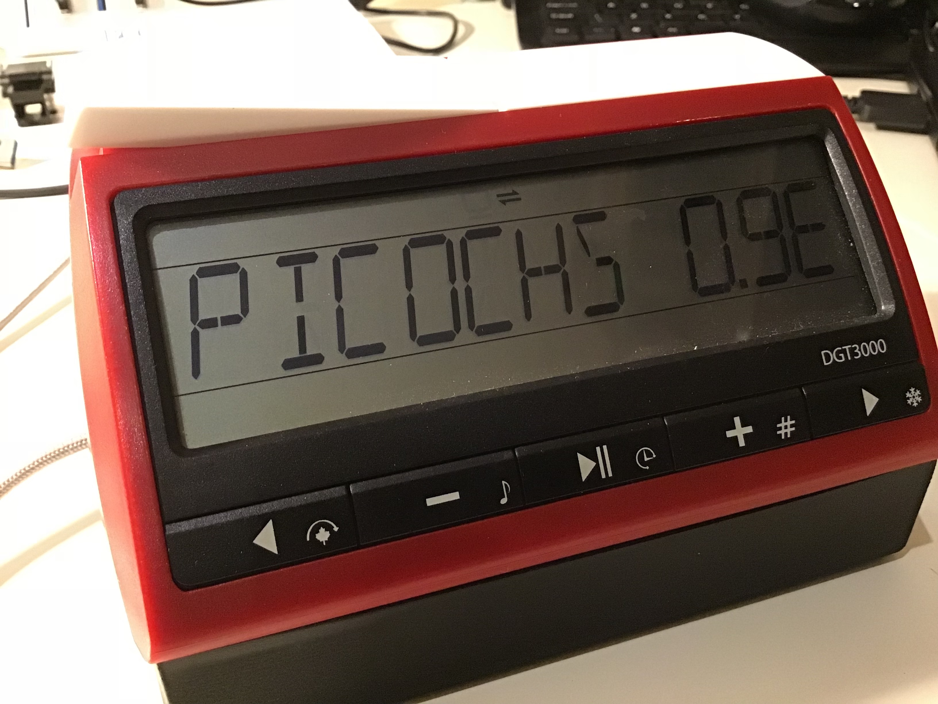
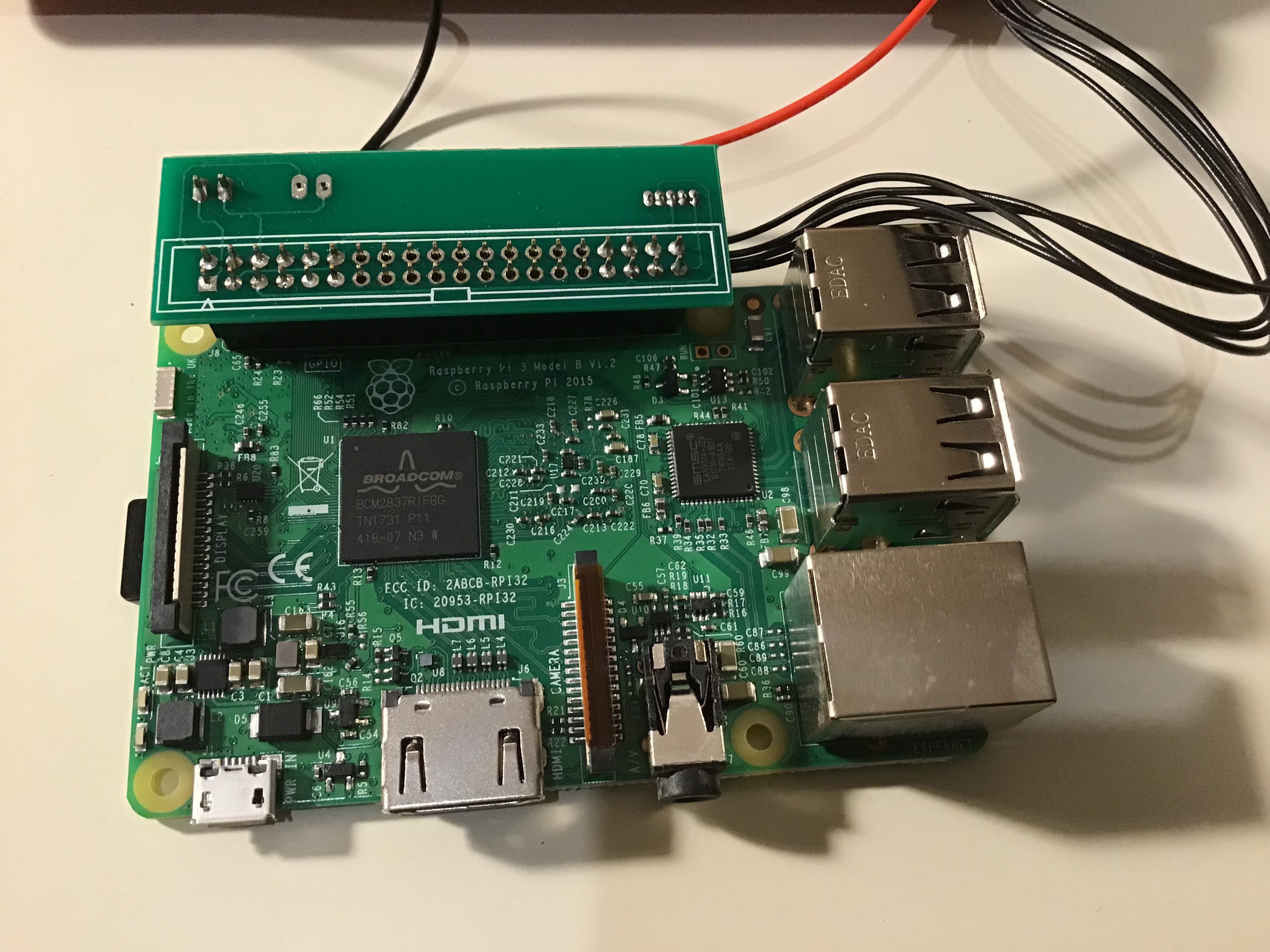
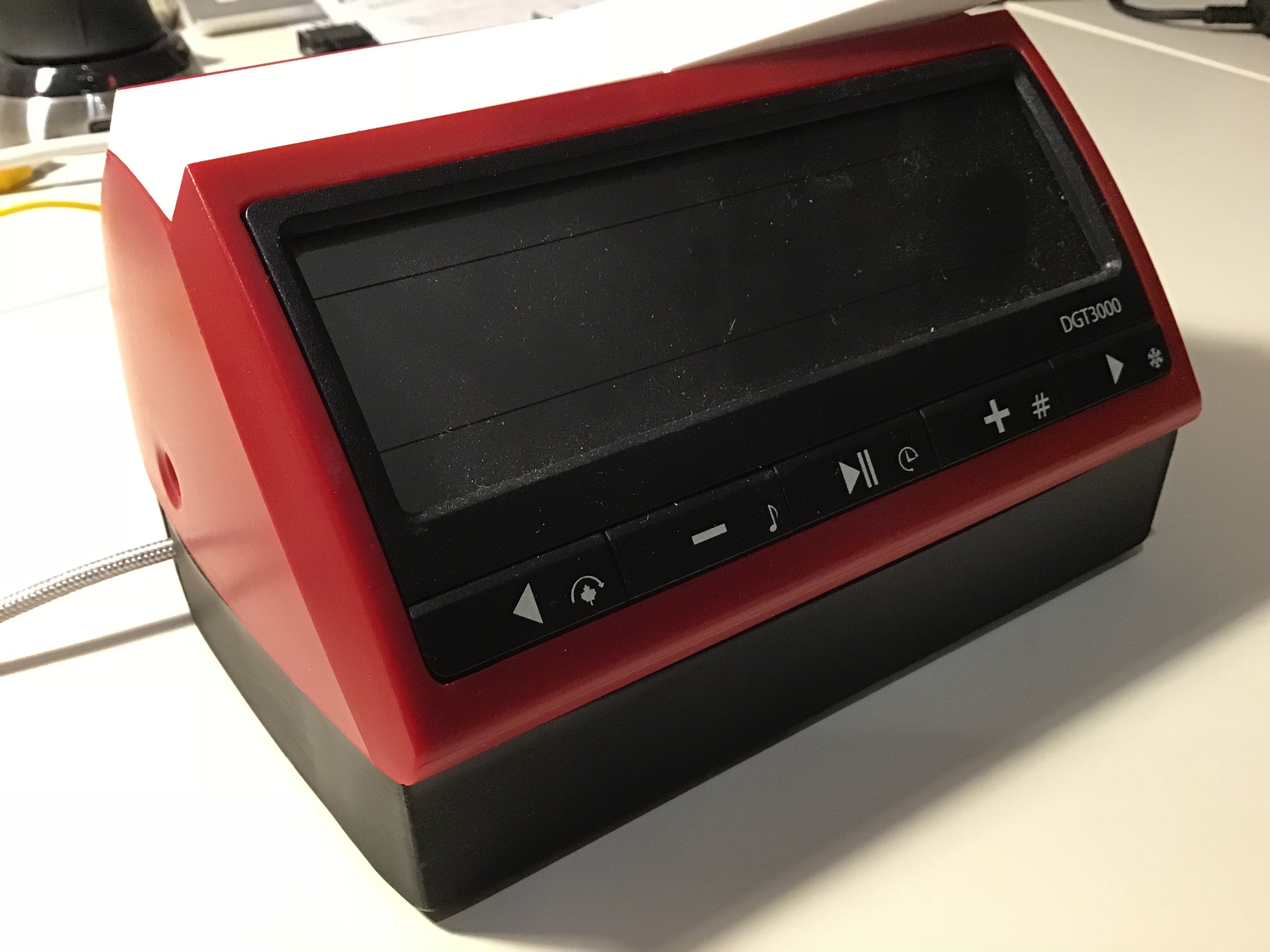
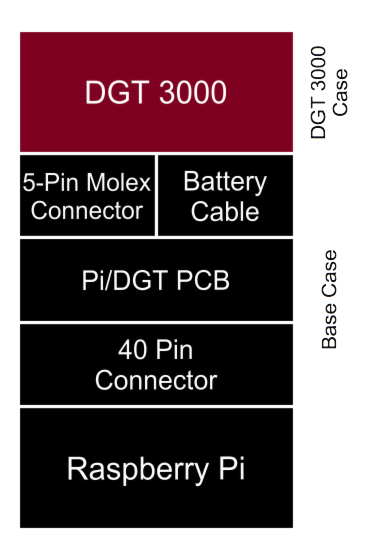
PicoChess is a software developed by Jean-Francois Romang that brings several chess engines to a DGT board and allow full control via the second queen (i.e. no cpmputer required!. It works with a Raspberry Pi and a DGT-3000 chess clock.
DGT offers an all-in-one solution (DGT-3000 with a Raspi) for £280. The DGT-3000 alone sells £50, so quite an up-mark for a £28 Pi!
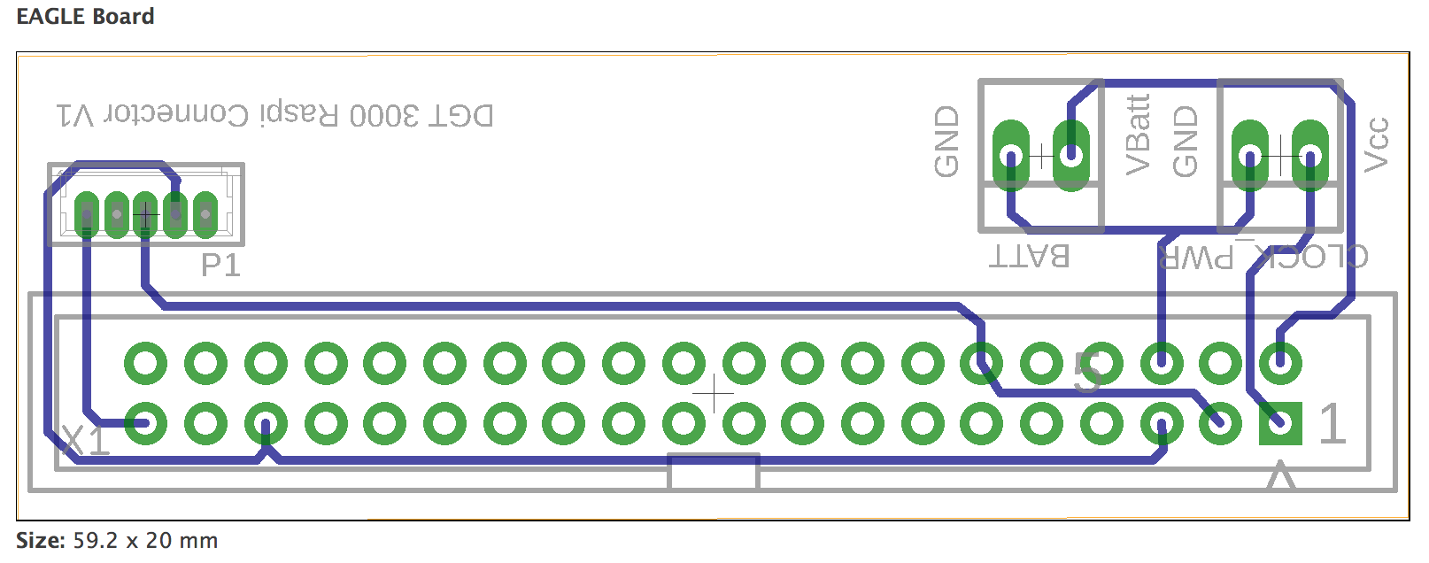
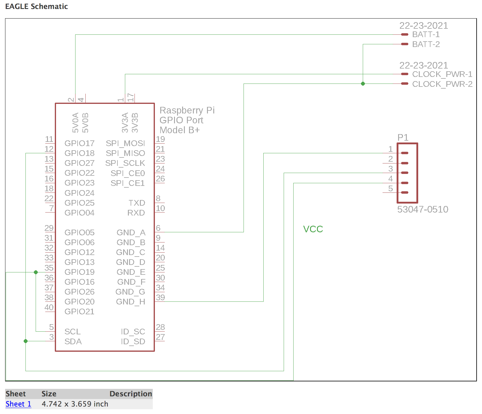
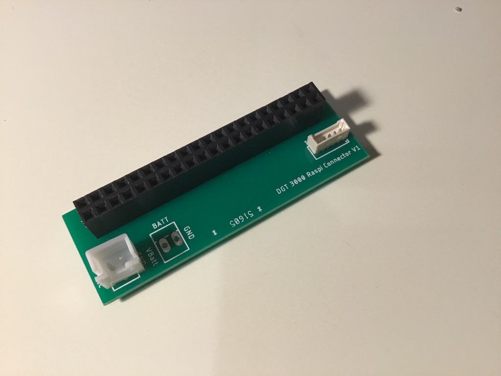
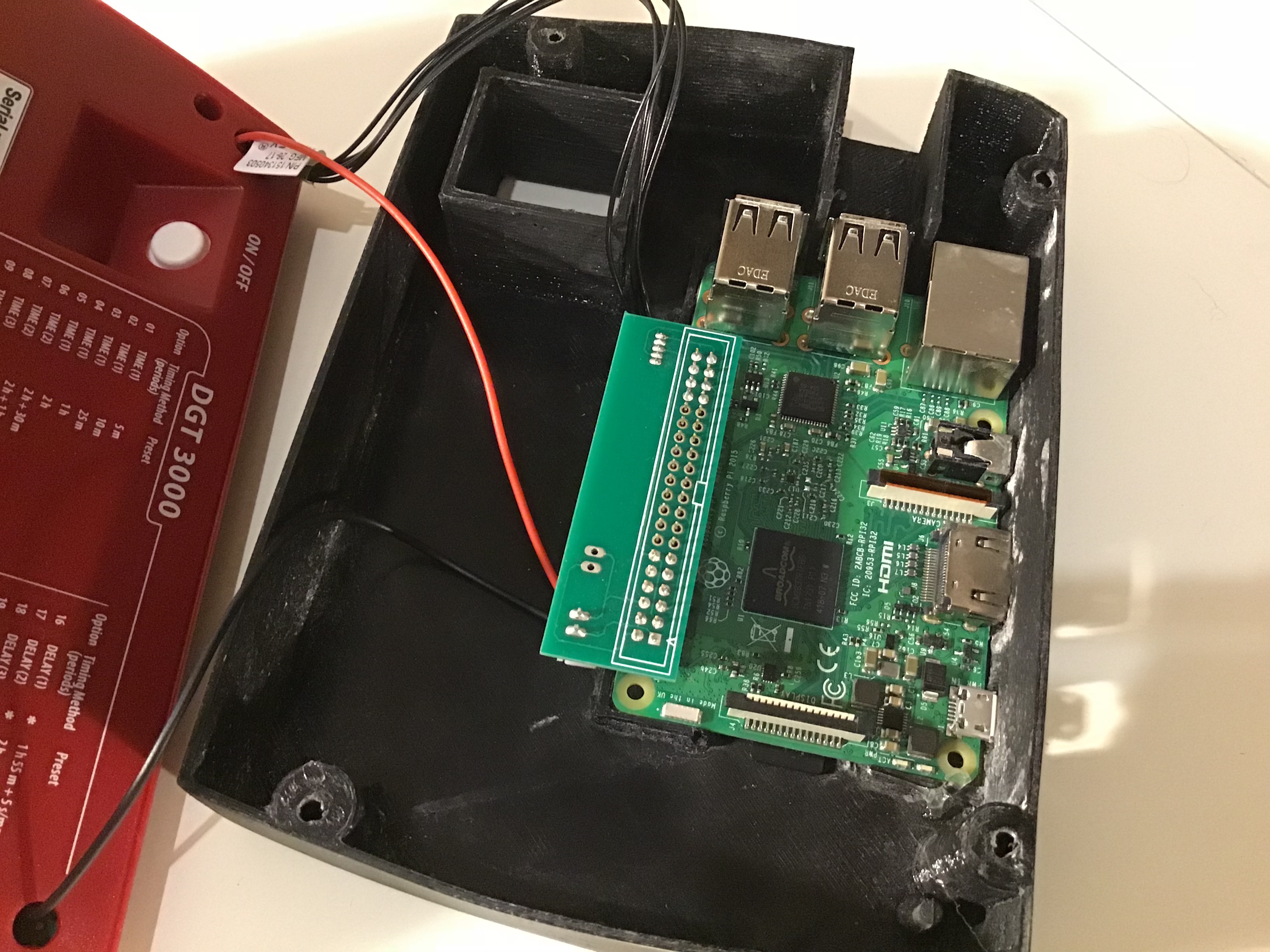
Based on the work others have done, I developed a board that allows you to connect a Raspberry Pi to the DGT-3000 without too much hassle. You need a soldering iron for the power cable (from the Pi to the DGT-3000).
The solution consists of the following components:
A DGT-3000
Raspberry Pi (a Raspi 3 will work best with the PicoChess engines, though a Zero W cor an older Pi can be used as well)
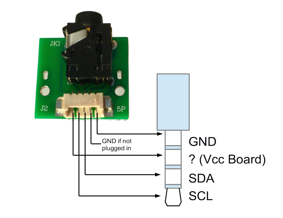
The connector cable (Pi-Hat with molex and power connector for the clock)
a 5-pin Molex connector cable
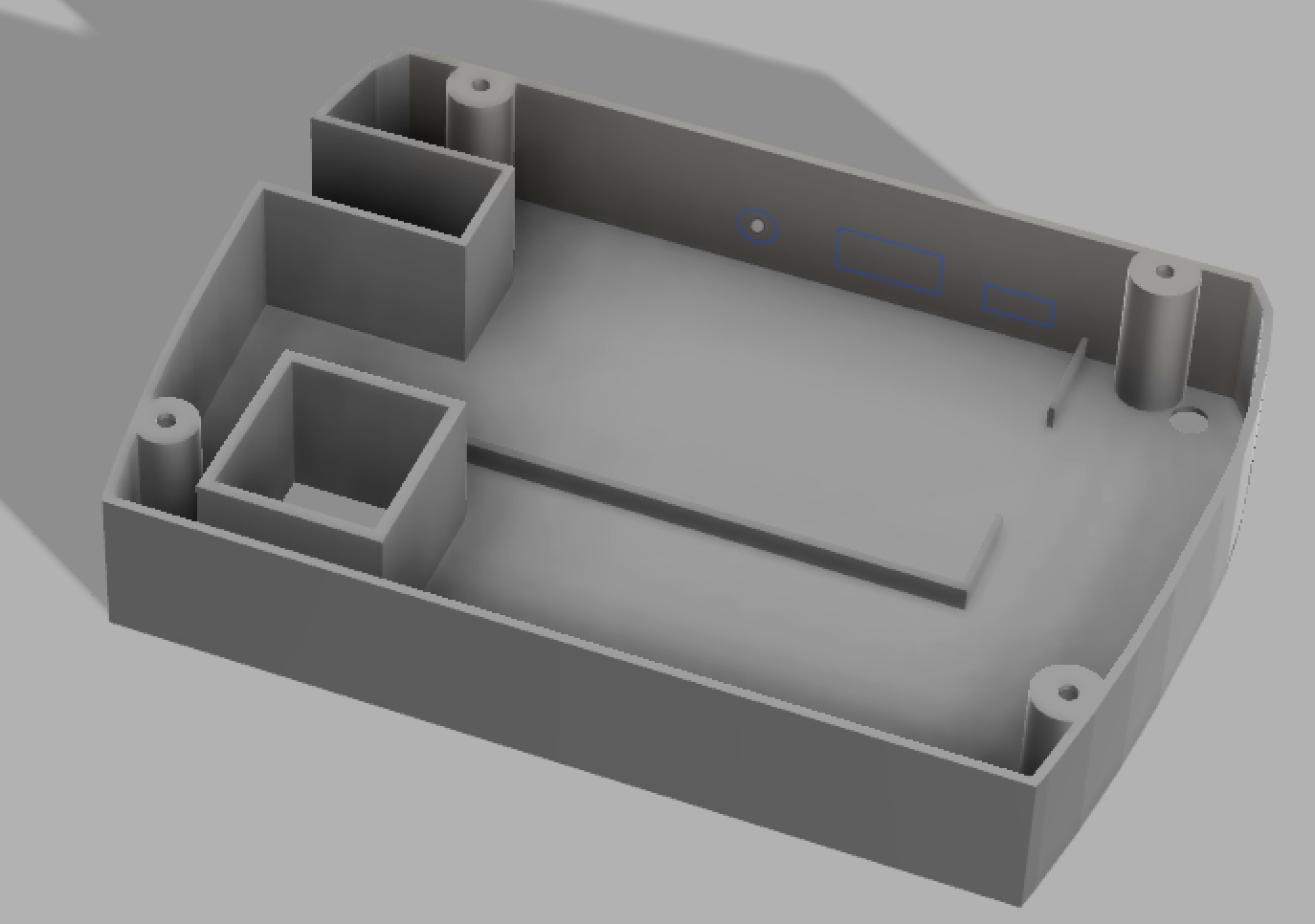
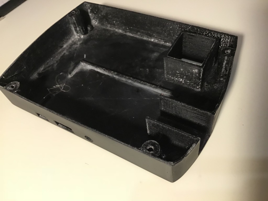
A Case that serves as a base for the clock and houses the Pi and the connector board
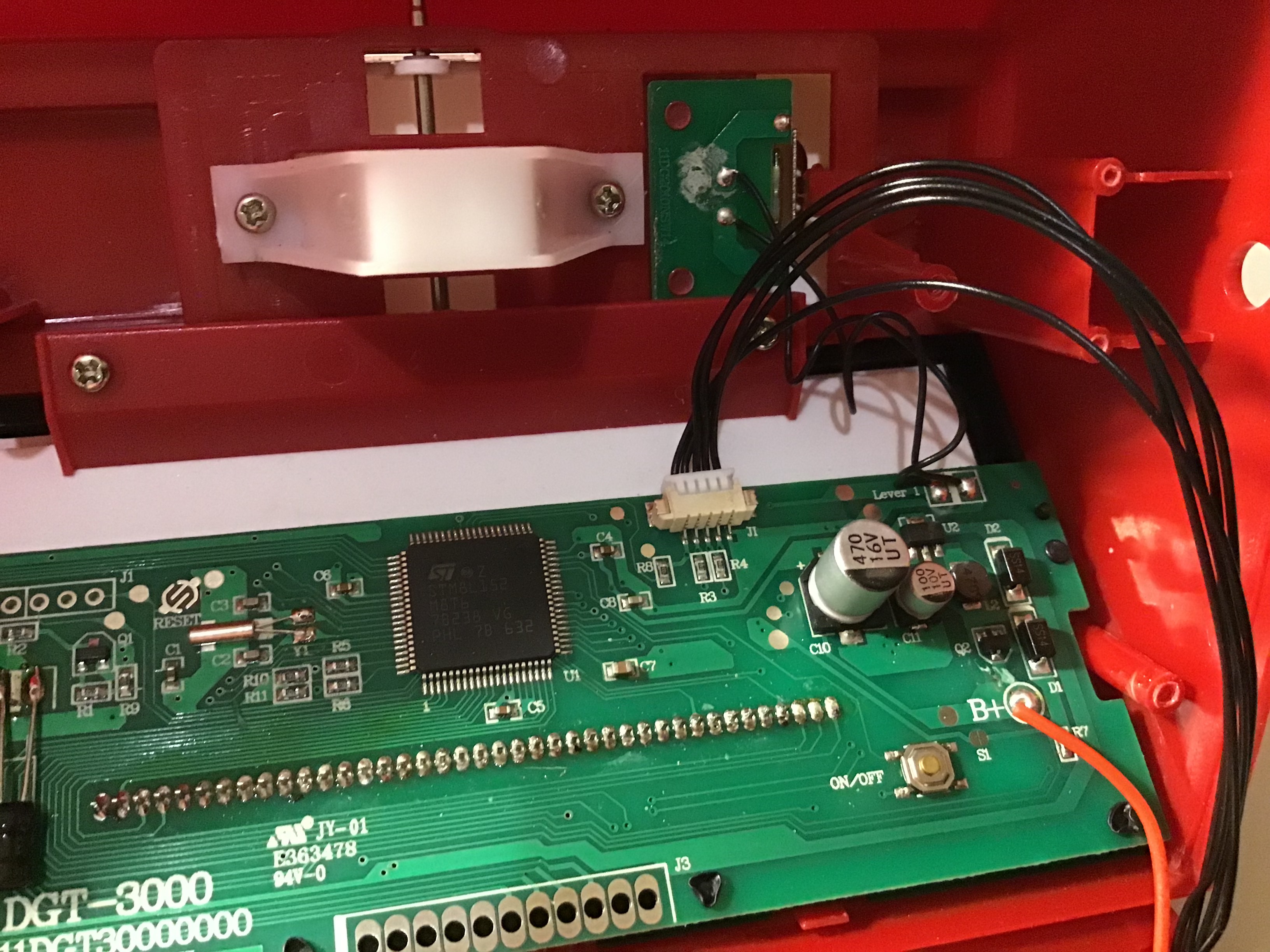
You remove the small board that holds the 3.5mm connector and instead the board will be connected directly to the RasPi via USB (I added a magnetic USB-C connector to easily hook up the board and the RasPi.
Just to clarify: After this conversion, you will no longer have the 3.5mm connector (and a little hole on the side of your DGt-3000).
Layout of the molex connector:
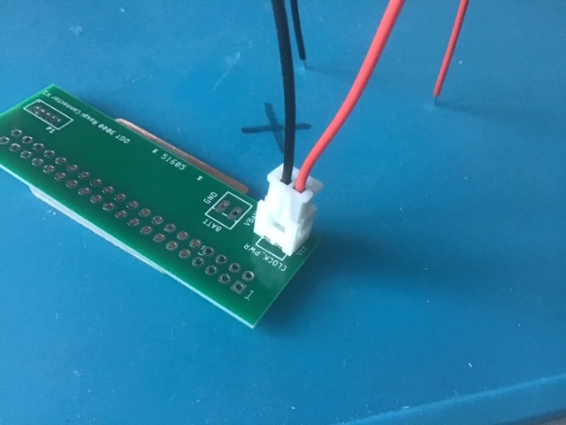
This is the layout of the board that connects the RasPi with the mainboard of the DGT-3000. The “Batt.” connector is optional. At some point I envisioned adding batteries to the case, but instead I just use a power bank to power the RasPi, which in turn powers the DGT-3000 clock and the DGT board (via USB).GerberEagle Files
In principle, you can mount the molex and battery connectors on either side of the board (rotate the connectors around the long side of the board, so they still connect to the same pads).
[5.Oct2019 correction:] The power cable that ships with the connector set that I offer on eBay requires you to mount the connector the other way around (nudge facing the 40-pin connector, second picture below). As a rule, always ensure that the red cable (+) is the one closest to the corner of the board.
A big thank you to Simon for making me aware.
Correct positioning of the connector/cable:
If someone manages to fit a rechargeable battery inside the case, please give me a shout: Resources:
Description (RS-Components)
Brand
Distributor
Part No.
Price [£]
Molex PicoBlade 15134 Series Number Wire to Board Cable Assembly 1 Row, 5 Way 1 Row 5 Way, 300mm
M2.2x20mm 304 Stainless Steel Phillips Countersunk Head Self Tapping Screw
I had a batch of the PCBs produced and am happy to sell them.
Search on eBay UK for DGT3000 PCB or the DGT3000 PicoChess Conversion Kit (Includes board, bottom case and cables. Not always available, contact me if you cannot find it).
Please note 75% of the proceeds go directly to Save the Cildren
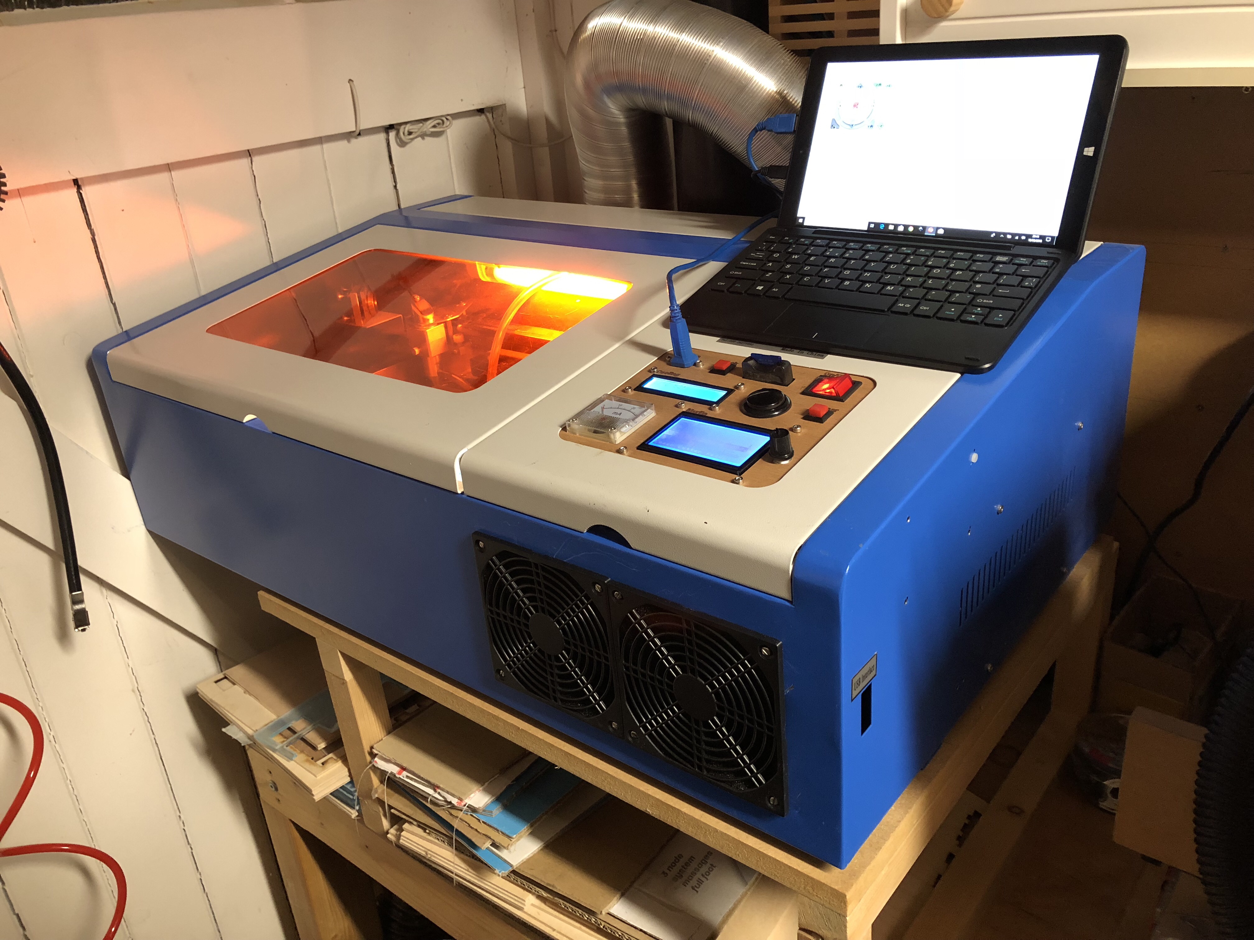
The K40 laser cutter is quite a bargain (I paid £350 for mine), but you get what you pay for. The cutter leaves you in many aspects wanting, and all these shortcomings combined will drive you insane, will frustrate you and limit your creative abilities.
Software/Hardware:
No air assist
Controller board / software simply sucks, i.e it is unusable, the license key is a pain
No GCode laser power control
No SD Card reader
Case:
No light in the work area
Unusable workpiece holder
Exhaust duct is too long, no usable connector at the back of the case, exhaust fan is unusable.
Cooling
No integrated heat exchanger
No coolant flow monitoring
No coolant temperature monitoring
Safety
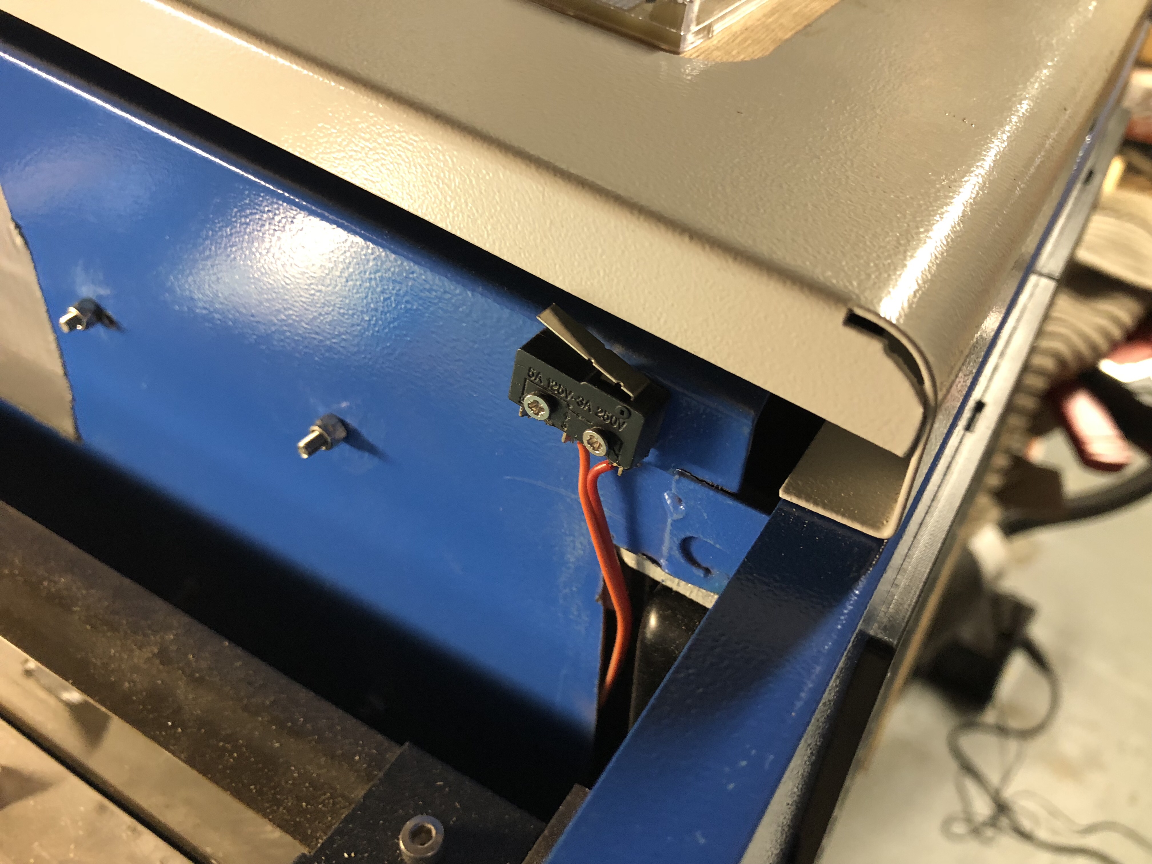
No emergency laser power-off when you open the work area lid
The good news is that there are solutions available for all these shortcomings:
Software/Hardware:
Replace controller with Arduino/Ramps HW and Marlin/Turnkey SW
Add garden pond air compressor and air-assist nozzle
Case
Add kitchen worktop light
Replace workpiece holder with aluminium plate
Shorten the exhaust inside work are, add 10mm exhaust adapter on outside
Cooling / Safety
Always wear safety glasses, ensure proper air ventilation, keep a fire extinguisher around
Add PC water cooling system
Add work area lid, flow and temperature monitor
I carried out all these upgrades over the course of a year or so, and my only regret is, that I did not do it sooner.
Based on my personal preferences and experience, I rang the air-assist and Arduino/Ramps upgrade highest, followed by work piece holder and heat exchanger. The rest is all good to have, but not as pressing.
You find plenty of videos and websites explaining the various options. Amazon and eBay are your friends.
A few observations:
A PC water cooler (2x 12mm heat exchanger plus high-volume dual fans, integrated reservoir and pump) keeps my system at 32 deg C during continuous use over several hours. System sits in my Garage, so ambient temperature is between 15-25 deg C.
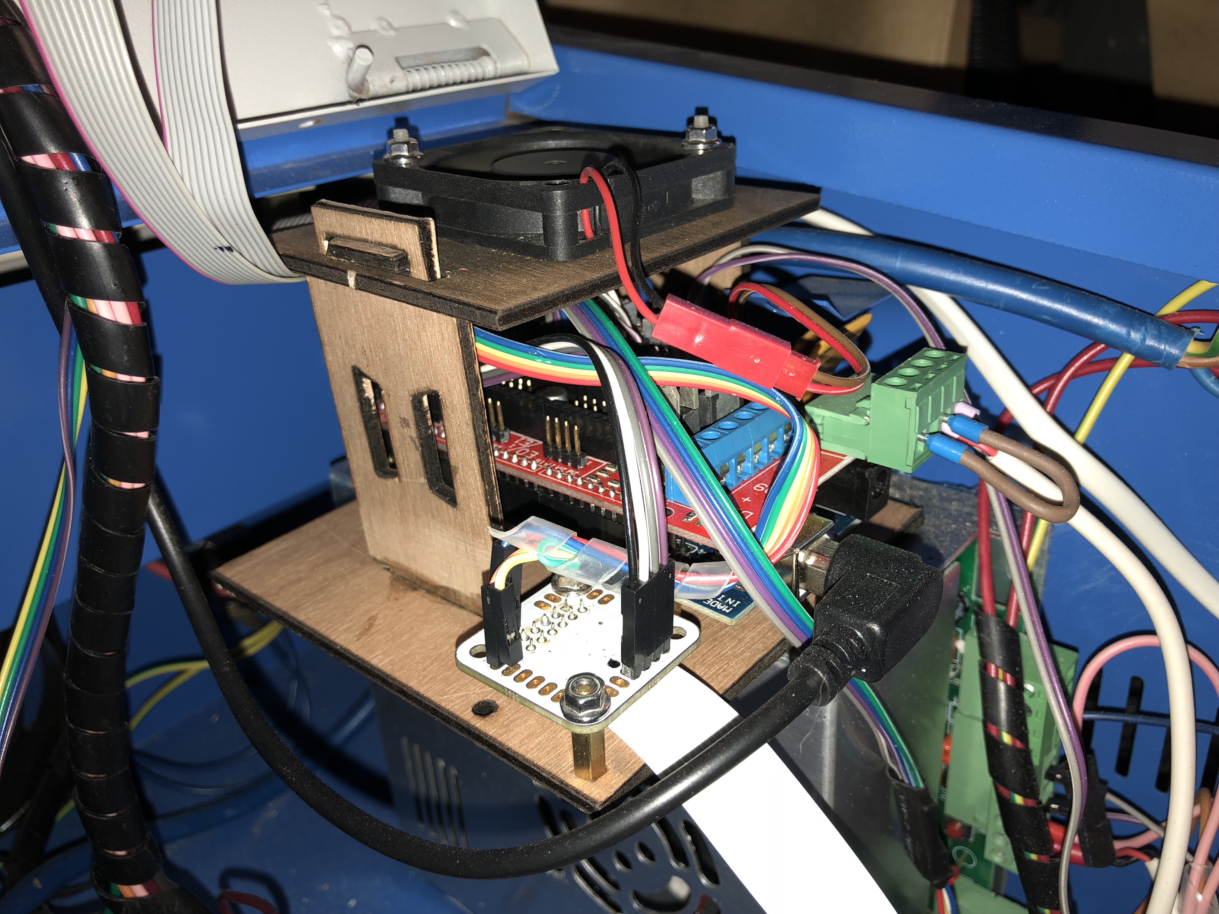
The “K40 Middle Man Board” (from OSHpark or look for my ebay item) made the Arduino/Ramps conversion much simpler. (OCybress posted the design. I ordered a few spares and started selling them on eBay for a donation to save the children to shorten the wait and included the connector)
I use 100% anti-freeze, since I do not always heat my garage during winter
I am paranoid about fires, so I also bought a CO2 fire extinguisher and fire blanket
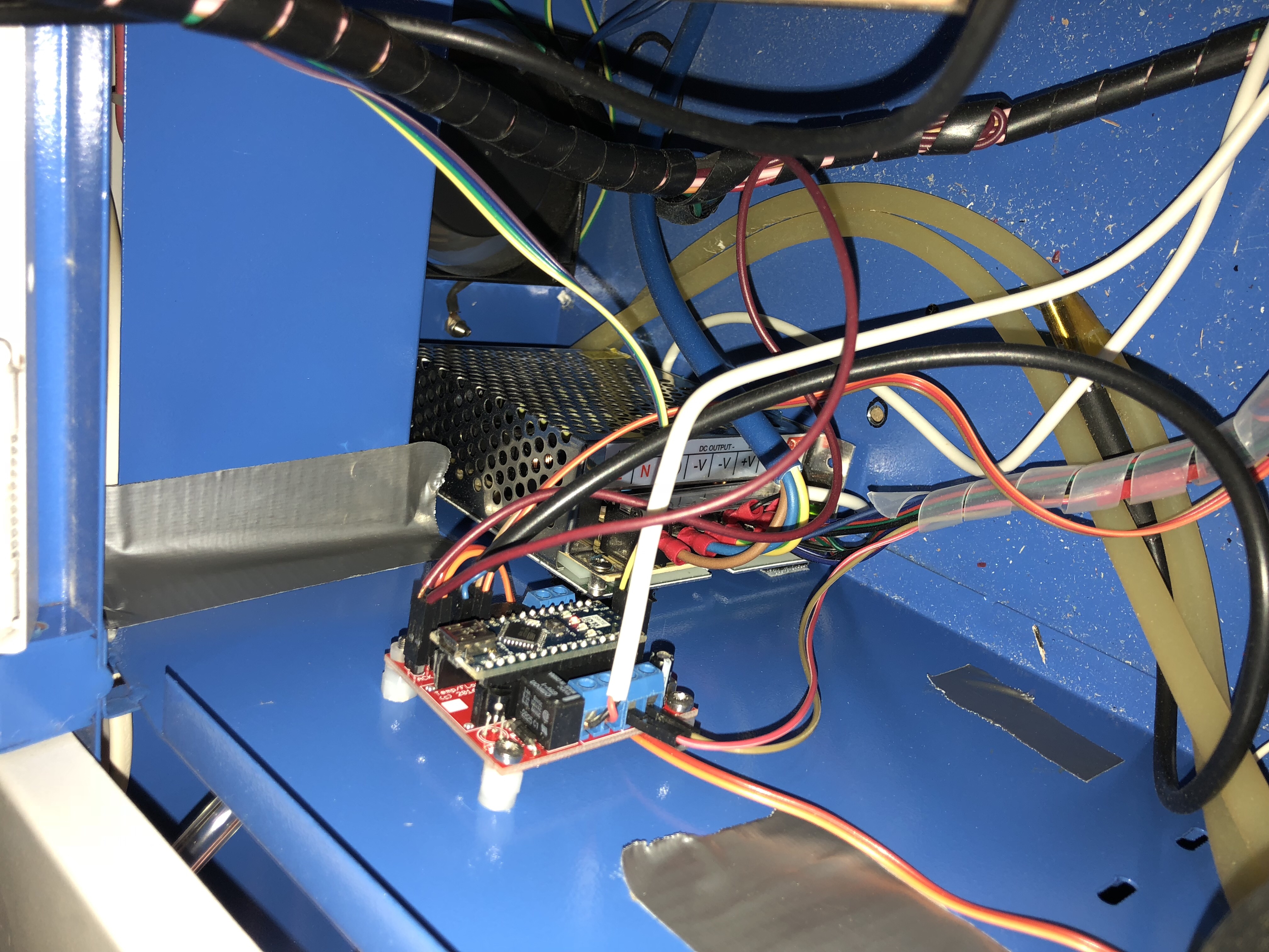
The safety laser power-off gives me some peace of mind when I am tempted to open the lid. Since I installed the system, I no longer open the lid, because it ruins the cut. Problem solved. An Arduino board monitors a lid-switch, coolant temperature and flow. It has a small display and a buzzer alarm.
I avoided cutting perspex when I started. Except for the smell, it is a much better material for laser cutters than plywood.
The turnkey plugin for Inkscape is not the most intuitive, but works 100-times better than the Corel software plug-in that comes with the K40. I had a strange experience where my scaling factors no longer worked, and a few weeks later I had to change the scaling factors back again. Never figured out what had caused this (I am running Inkscape in X11/XQuartz on OSX).
I design in Fusion 360, export sketches as DXF, import into Inkscape, adjust layers and resolve objects into components, convert objects into paths, generate GCode and use Pronterface on an el-cheapo Win10 tablet (£150) to control the K40 (a Raspi could probably do that job just fine, but sometimes I want to use Inkscape in the workshop to make some minor adjustments)
Below are some pictures. Feel free to contact me if you have any questions.
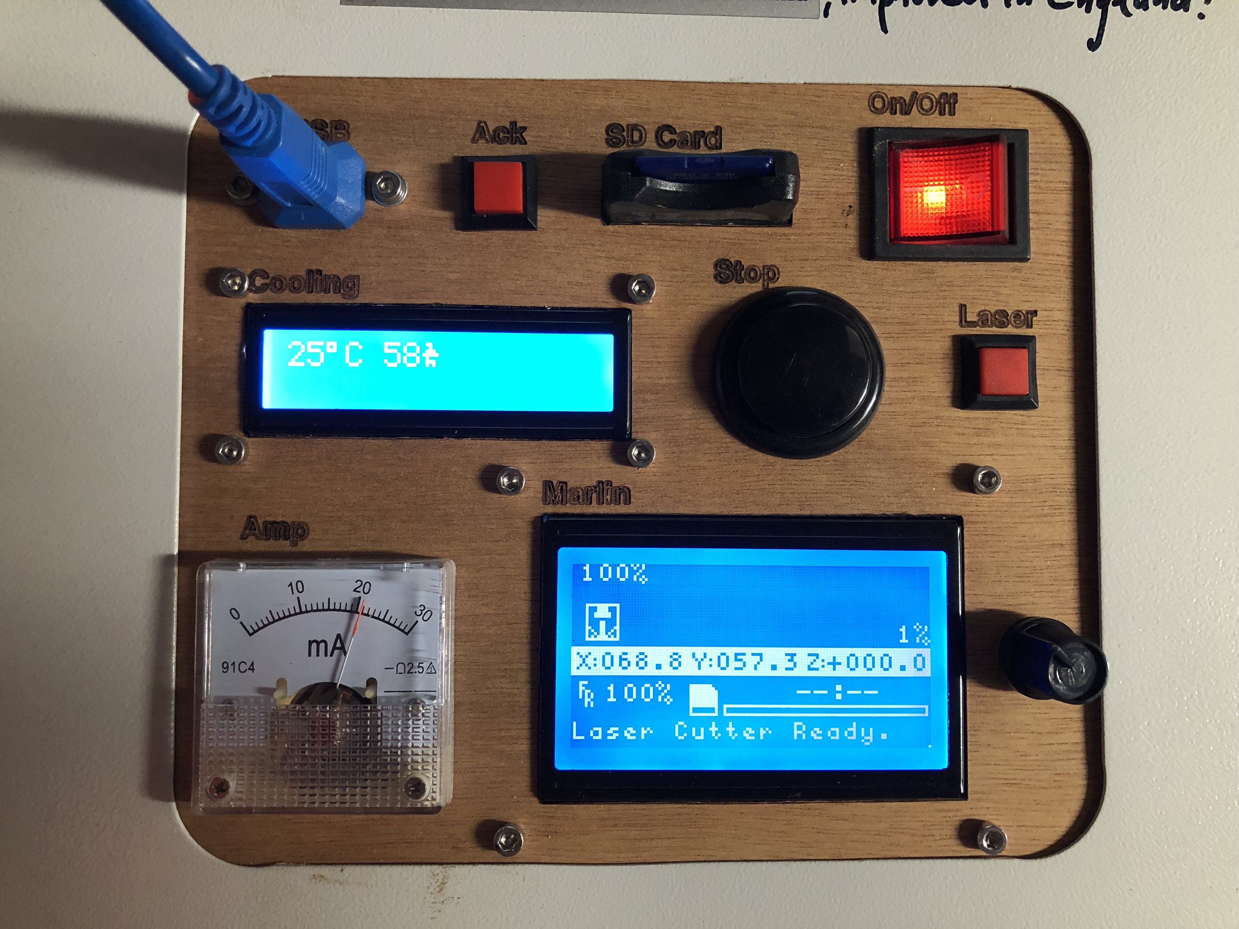
Control panel with monitor-display and the ramps display.
The “Ack” button resets a temp or flow alarm. Search long enough on AliExpress and you will find the exact buttons that the K40 comes with.
I use USB and SD reader extensions
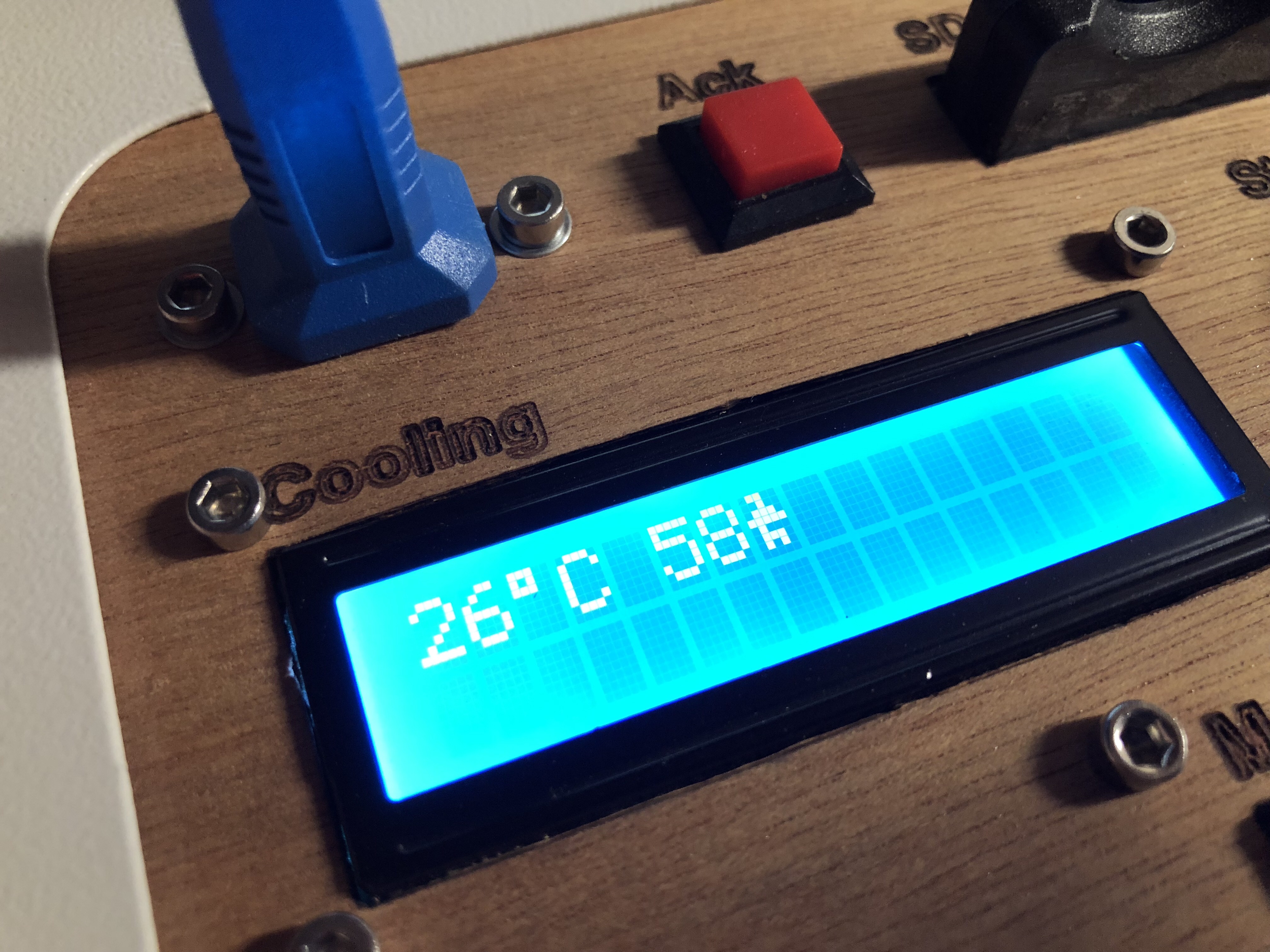
Coolant temperature and coolant flow :
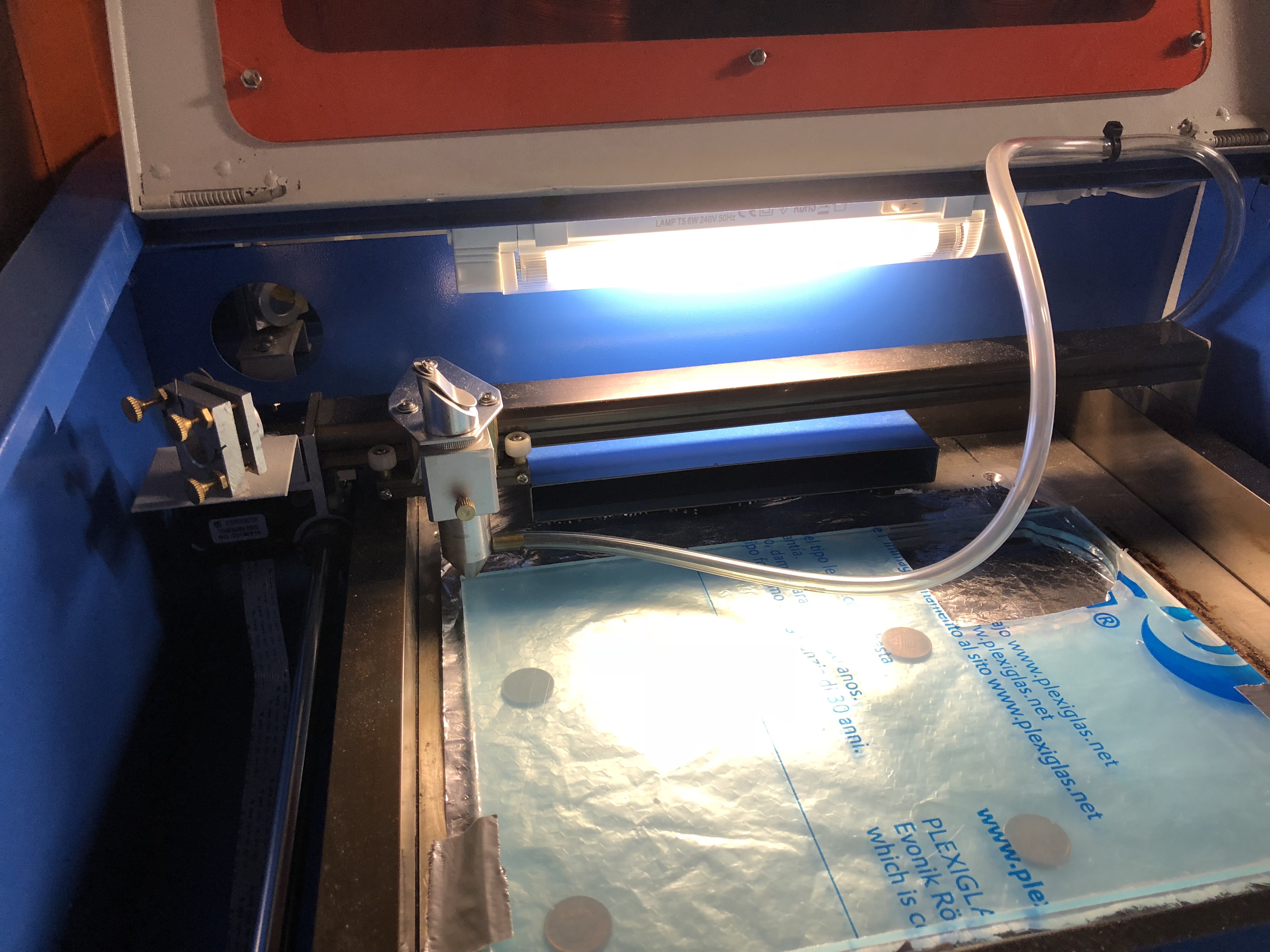
work area light:
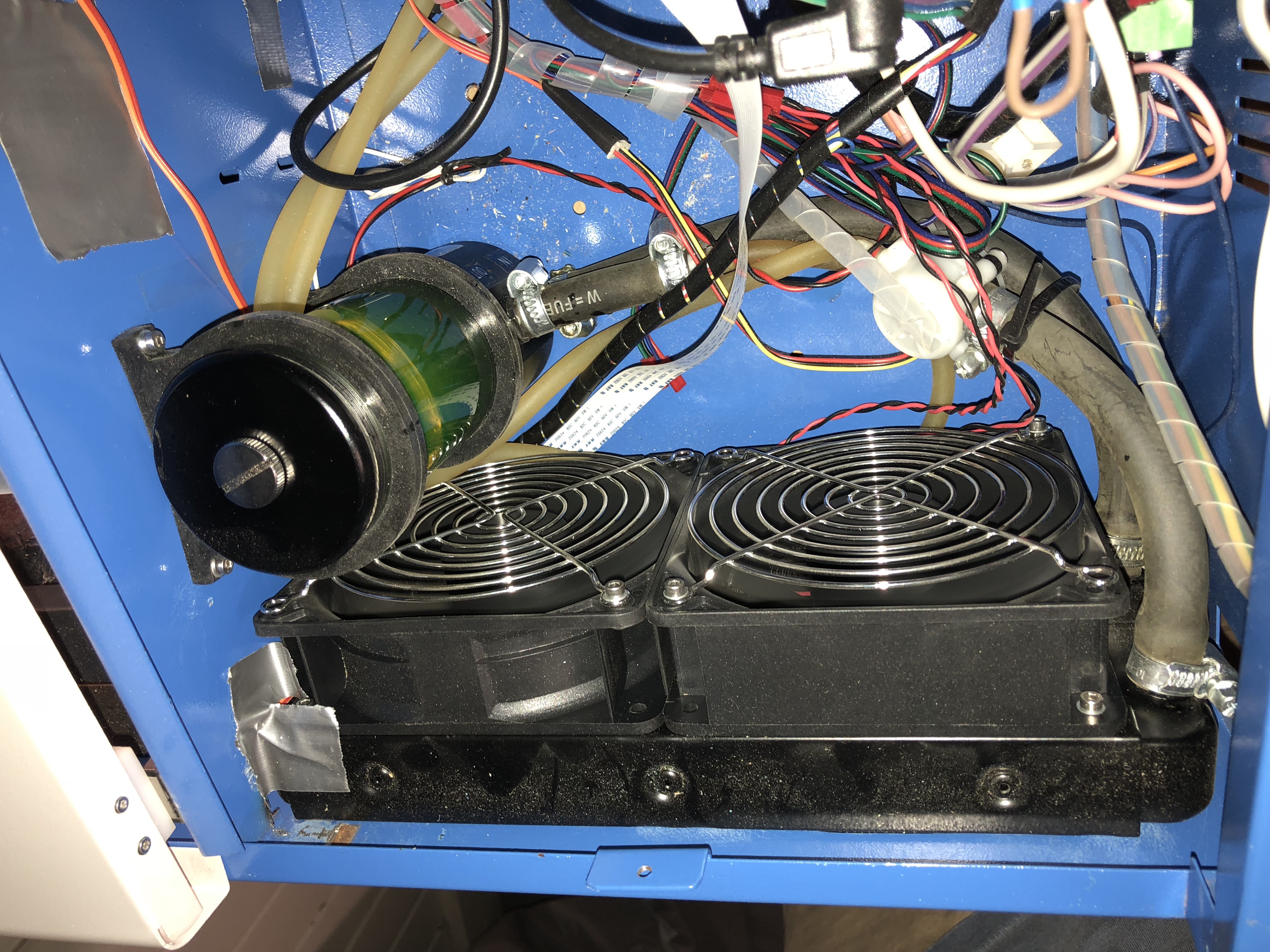
Cooling fans, heat exchanger and reservoir/pump. The green stuff is the antifreeze:
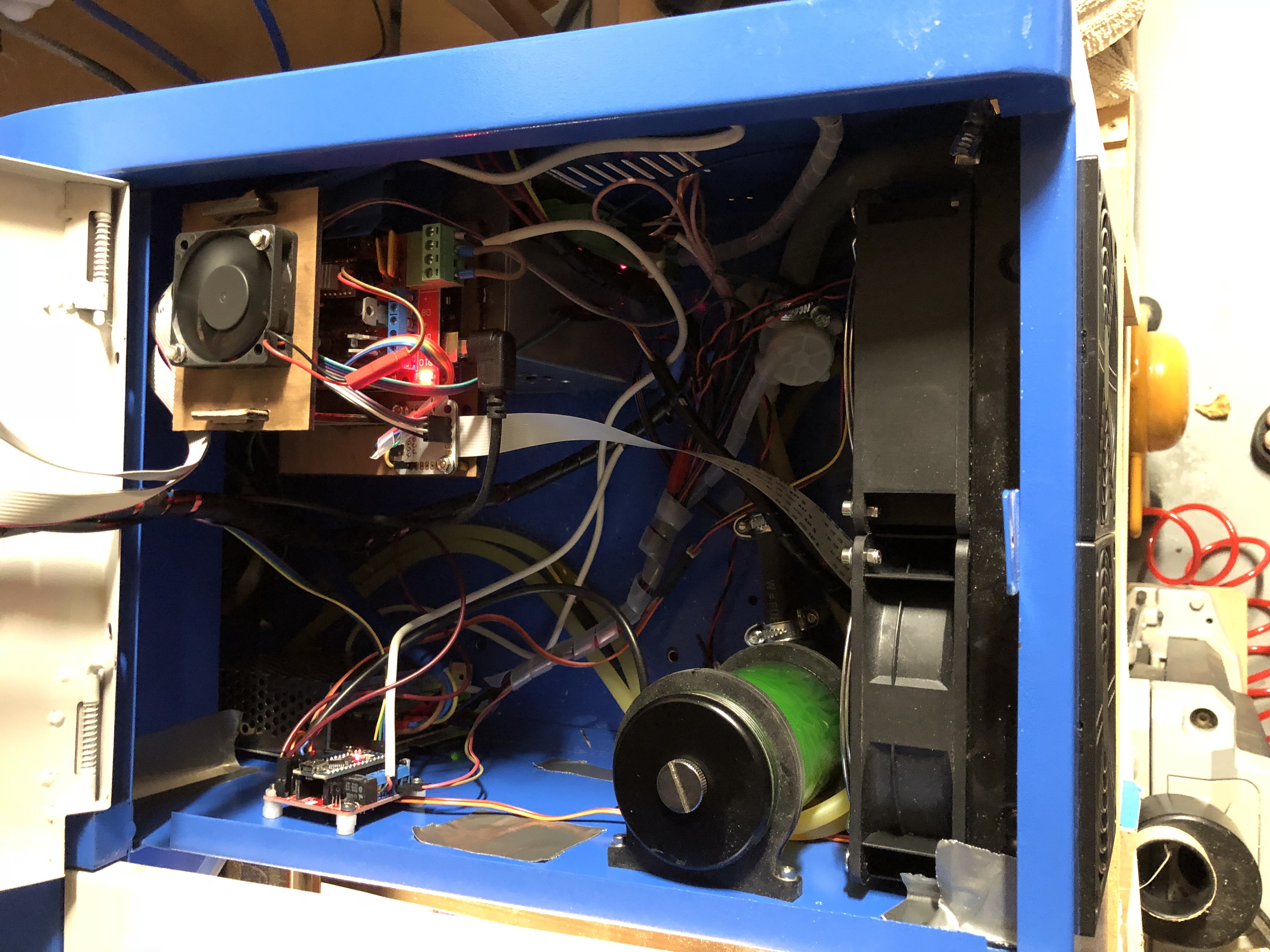
Once you rip out the old board, the right cabinet offers plenty of space. It can possibly also fit the air compressor, but I wanted to keep the vibrations away, so I installed it under the table the printer sits on:
Middle Man Board in action:
This is the control board for the lid-power-off, flow and temperature monitor:
This is the switch that watches over the lid/cover:
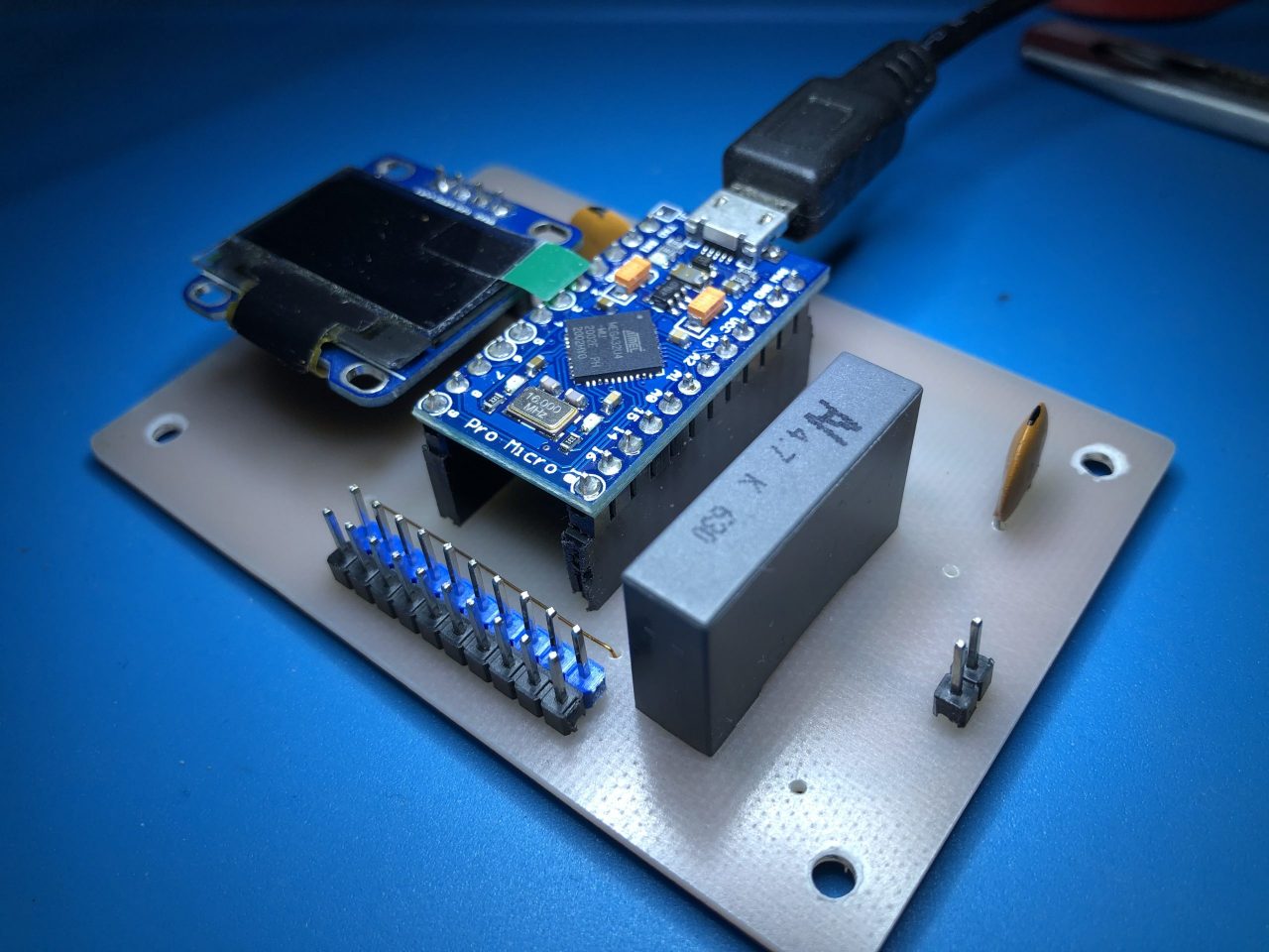
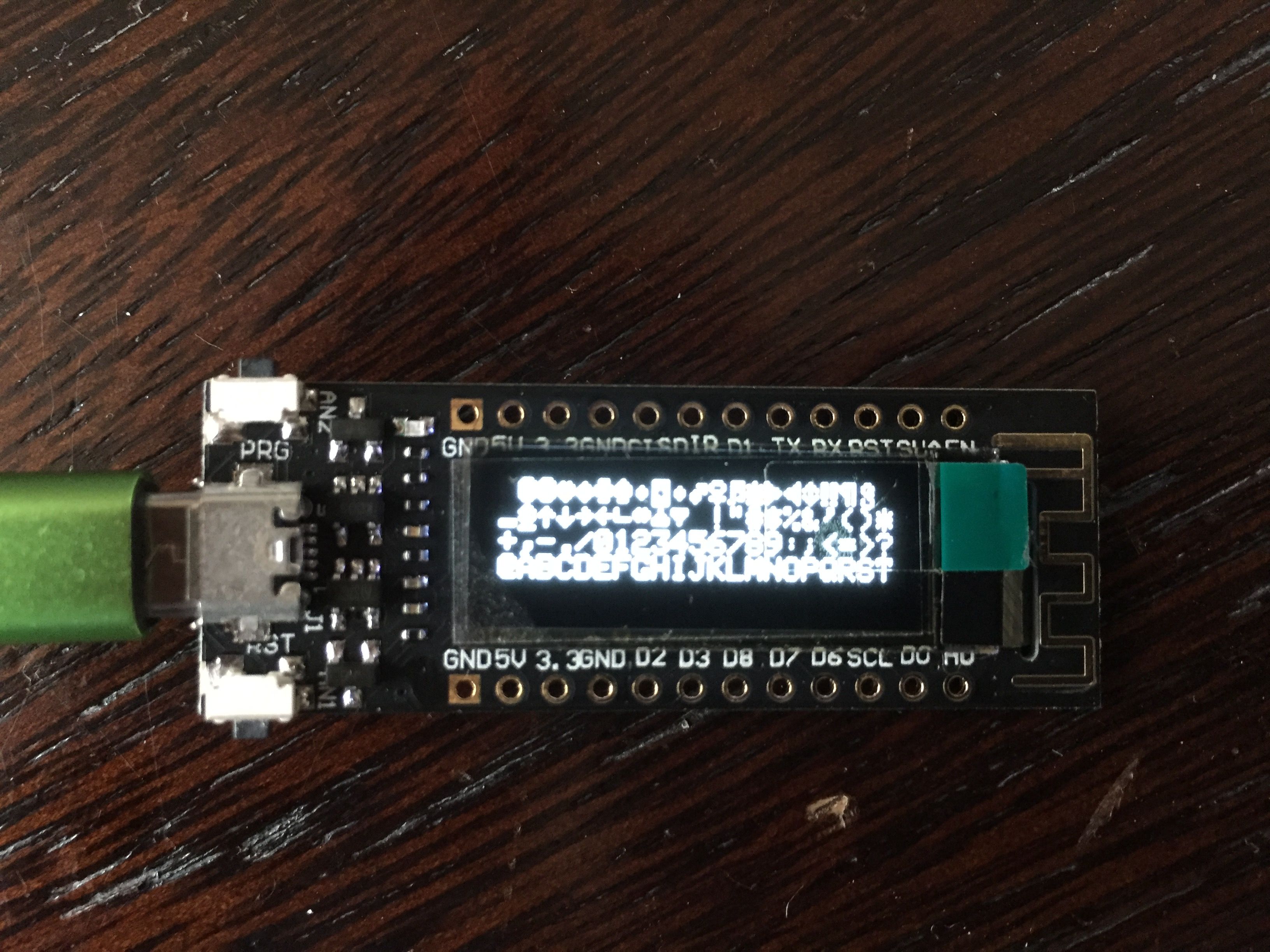
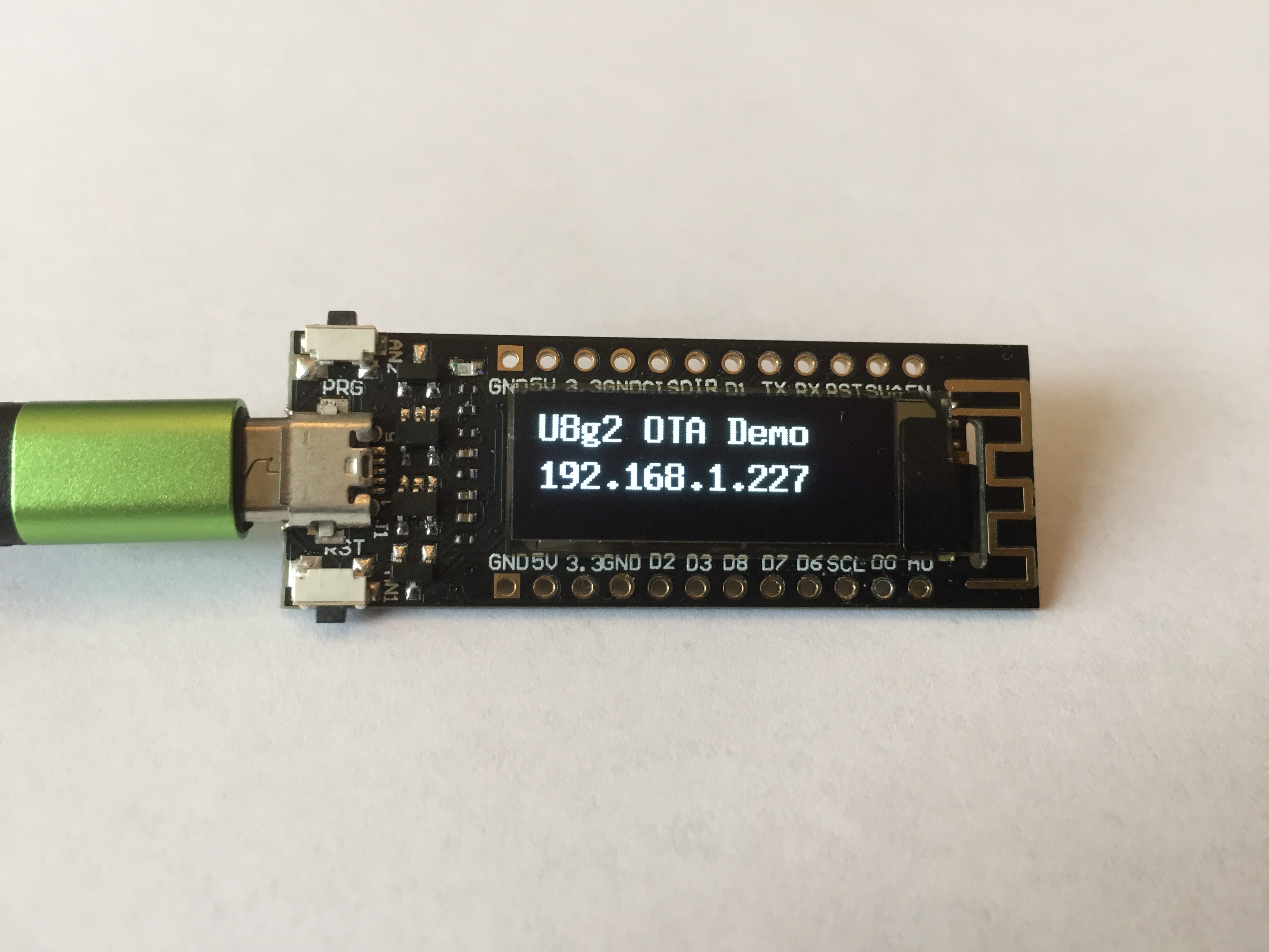
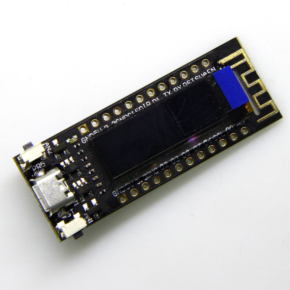
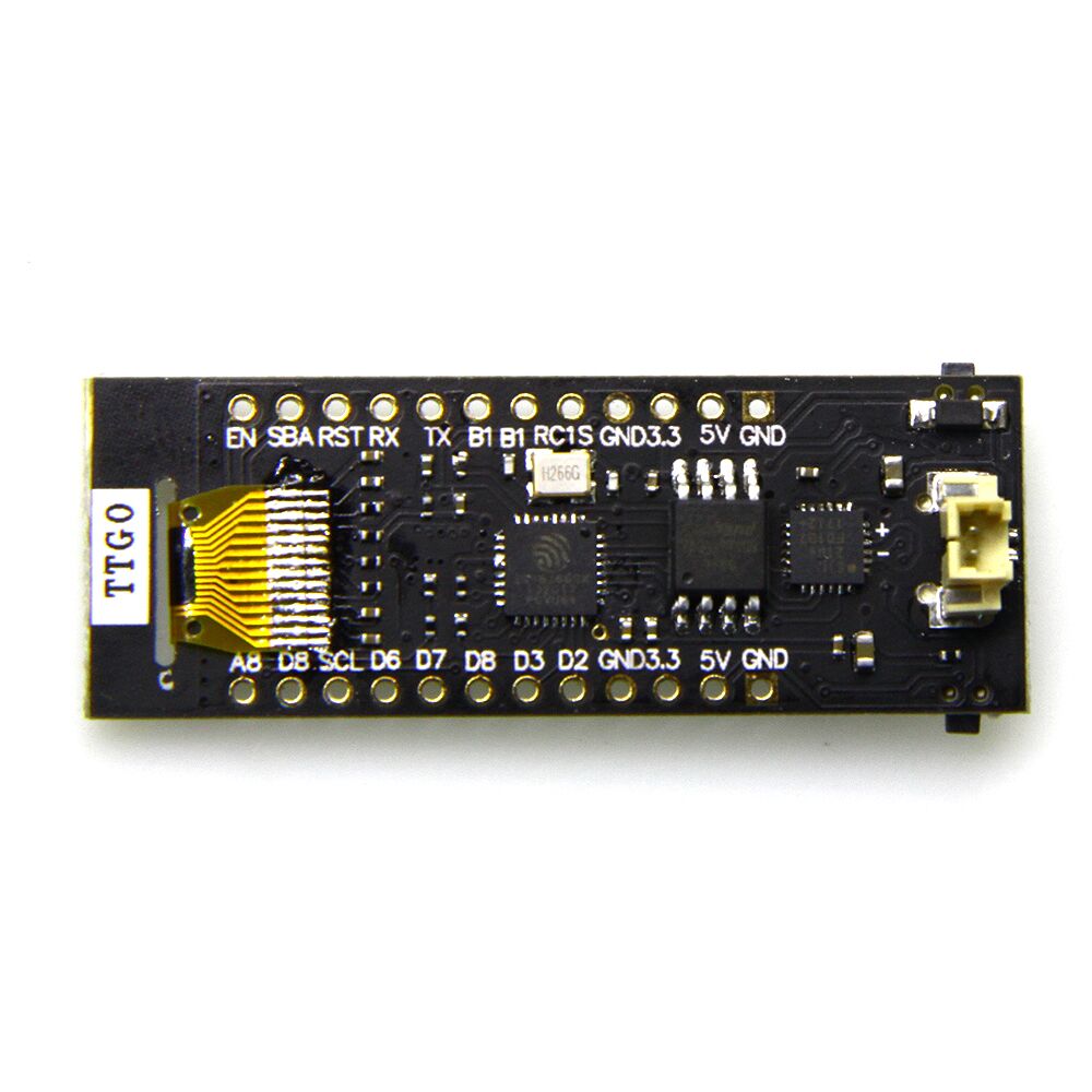
Sites in China and eBay sell an ESP8266 module with 4MB flash and a build-in 0.91″ monochrome OLED display and a rechargeable battery port.
Display
The display is a 128×32 pixel display connected via an SSD1306 controller.
It took me a while to figure out how to get the display to work – the Chinese sellers provide a rubbish demo script that uses the wrong pins for the I2C interface to the display controller.
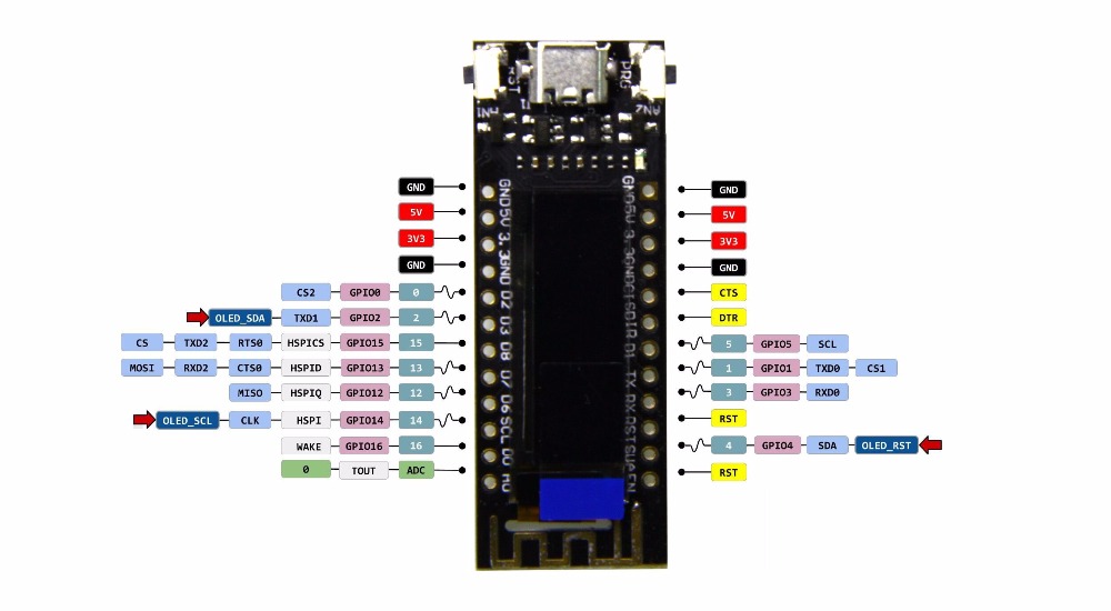
The following pins and library combination works well:
The antenna gain seems to be quite poor – I noticed the module loses connection to my AP about at half the distance that my ESP8266-12 or ESP8266-01 modules tolerate.
I successfully managed to run OTA updatable code (see example).
Layout
The board layout is a bit unfortunate as so far as the micro USB connector is mounted on the top, protruding in height above the display, which will not allow to mount the module flush against the top of a case.
Two buttons (reset and GPIO01) allow to invoke flash mode and reset the device, which comes in handy during development.
The pins are labelled both on the front and back side of the board.
Price
At time of writing, the board can be bought between $9 and $12 from Chinese sellers and for $15-$20 from Western distributors. The ones I bought came with a plastic box, a battery cable and connector and pin headers (not soldered)
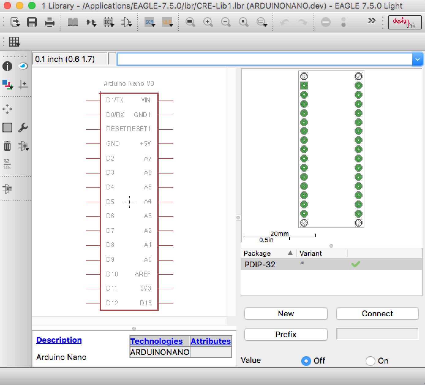
This is based on Warren Brayshaw’s post here, which seems to have the A0-A7 lines reversed (compared with the Nano V3 . Maybe it once was correct for an earlier version of the Nano – I don’t know). The library below has been updated to be consistent with V3. The ICSP headers are not included, just the headers on the long sides of the nano board.
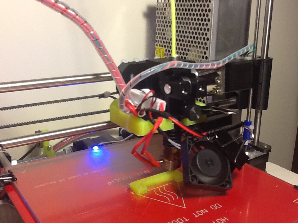
The Wade extruder on my i3 started to slip and not enough filament was extruded, so the prints started to look flakier and flakier. I checked the extruder, refurbished the hobbled bolt, but the problem came quickly back. Only once I increased temperature to over 230C (for PLA!) it completed prints – of course the result looked like roasted marshmallows.
So I ordered a new J-Head hot end (0.4mm) and a new all-metal extruder. Price on ebay was $175 plus $20 shipping. Quite steep, but I have no regrets! Build quality is excellent and the Nema 11 stepper has plenty of power thanks to the gearbox (at first, I used same driver setting as for my Wade extruder’s Nema 17 and subsequently the stepper would become very hot. Adjusting the reference voltage of the driver board to 0.45V solved the problem).
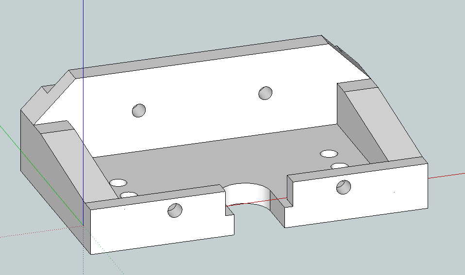
I had to print a new mount to fit the extruder. That was a bit of a challenge, given I own only one 3D printer, and that one was broken. I managed to get one decent print: enough to mount hold the new extruder in place. Once I had the printer re-adjusted (M92 X80.00 Y80.00 Z4000.00 E1333.33), the first task was to print a better mount.
Result is attached below.
Metal Extruder
Not sure if it’s the new extruder or the recalibration of the machine (incl. resetting x and z end stops), but now I am finally able to print straight onto glass (using a watered down PVA solution to improve stickyness).
Details for the mount are attached. I had to move the extruder a bit further out, so the Nema 11 motor would not crash into the right Z-thread.
Printing a fan mount is next. The extruder has two M3 holes at the front, that can be used to attach a fan (surely they were put there for something else, but they work just fine).


