ESP32 LoRa GPS Range Tracker – Part 1

The outset

A few months ago, I installed a LoRa Gateway and I was able to talk a friend into setting up a second gateway. Both are connected the TheThingsNetwork.org.

The idea is to build cheap, simple sensors for all sorts of stuff (temperature, rain, wind, usage of the football goals) and place them around our village (garden, school, commons, etc.).

The problem

But we do not know the range of our gateways just yet. Of course, we could get in our car with a simple module and drive until we lose connectivity. But where is the fun in that?

So the plan is to build a GPS enabled LoRa module, that logs the signal strength and allows us to draw a heat map of LoRa coverage in our area. It should also allow us to test different antennas and understand better how they influence the range.

The solution

An ESP32 with LoRa and display was sitting in my drawer and I ordered a GPS/GLONASS module from AliExpress. Everything us assembled on an impromptu test rack, ready to e powered by a USB power bank.


(The big yellow knob is a rotary encoder)

Next Steps:


    • Get the GPS to work (fuGPS library)
    • Get the display to work (U8g2lib library)
    • Connect the rotary encoder
    • Implement a menu system for parameter editing and control (ArduinoMenu library)
    • Figure out how to derive meaningful signal strength data from the LoRa transceiver
    • Connect an SD Card reader and log GPS and LoRa data
    • Do some wardriving and create a heat map of the area

DGT-3000 Raspberry Pi Connector

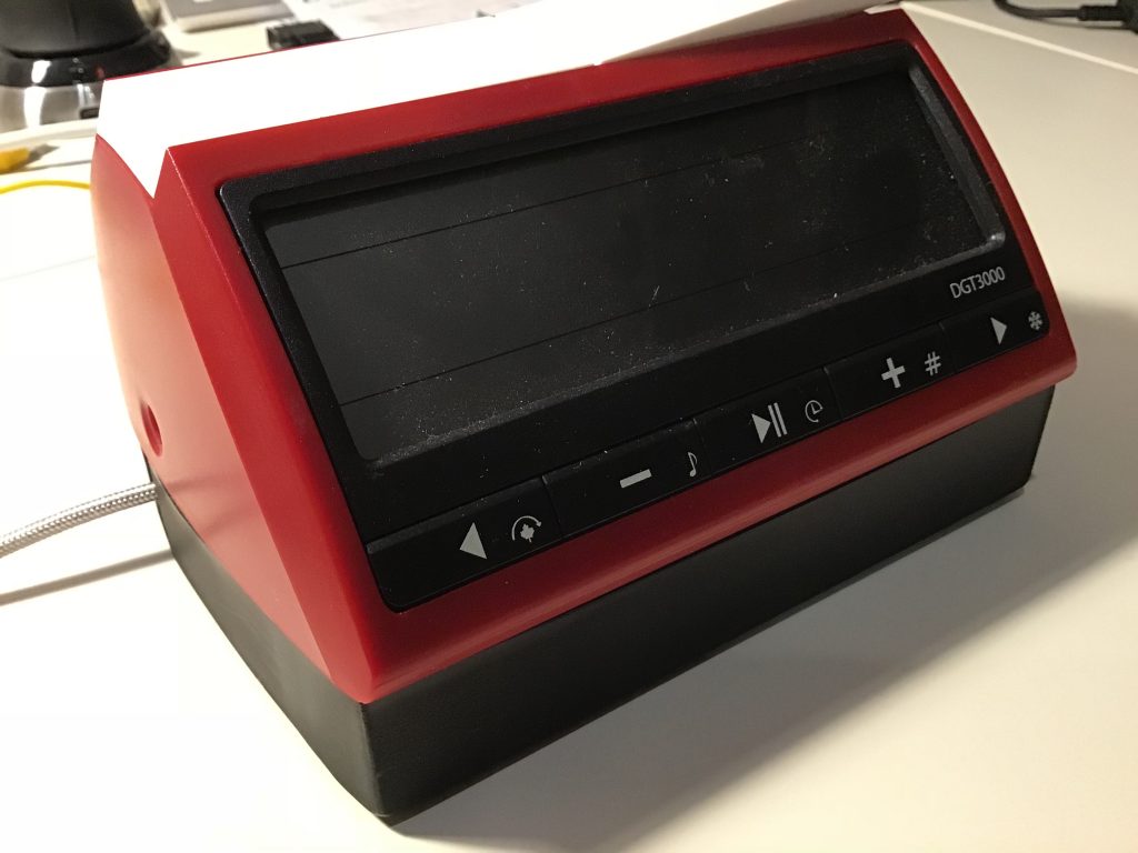
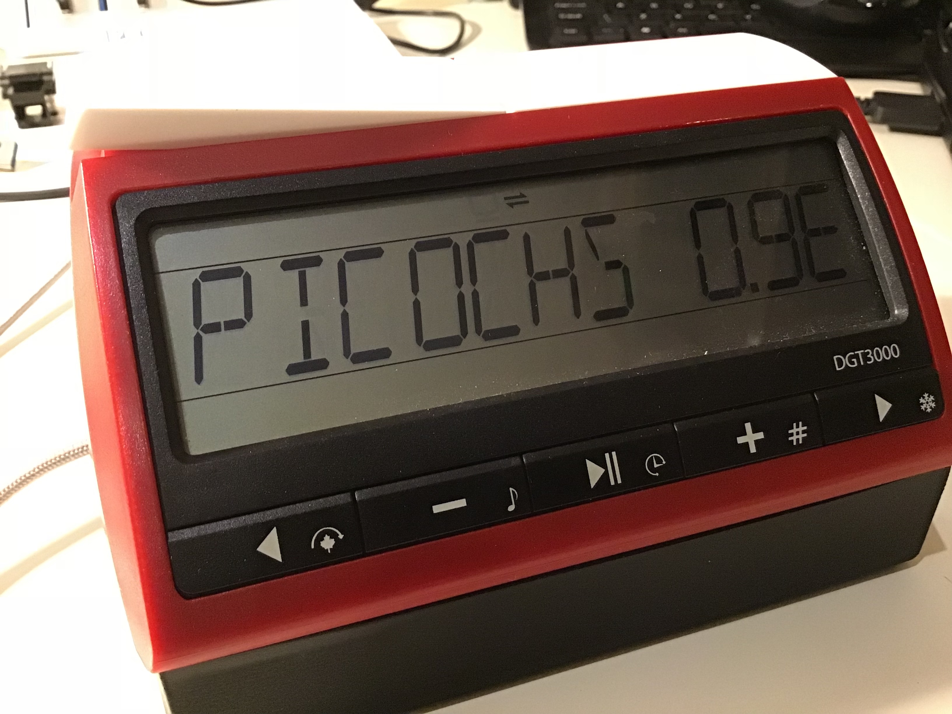
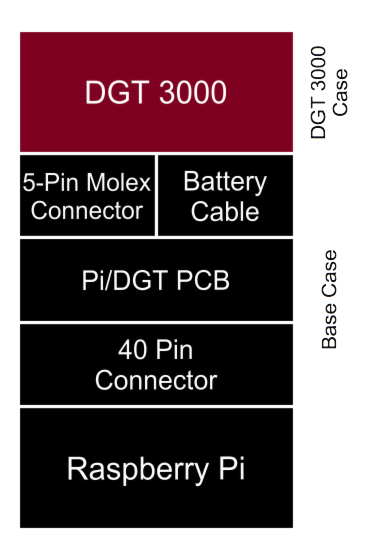
PicoChess is a software developed by Jean-Francois Romang that brings several chess engines to a DGT board and allow full control via the second queen (i.e. no cpmputer required!. It works with a Raspberry Pi and a DGT-3000 chess clock.

DGT offers an all-in-one solution (DGT-3000 with a Raspi) for £280. The DGT-3000 alone sells £50, so quite an up-mark for a £28 Pi!

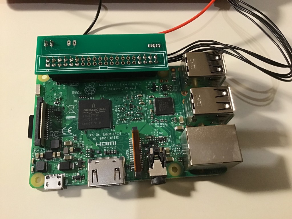
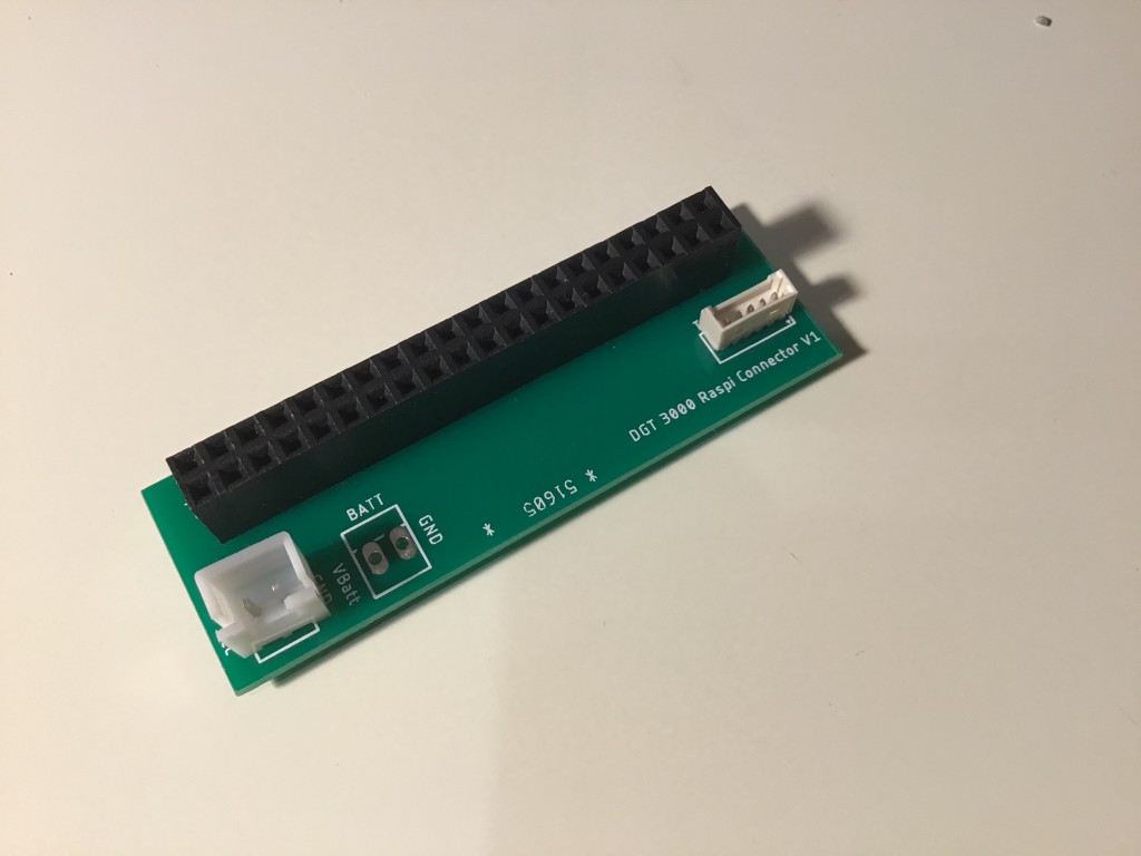
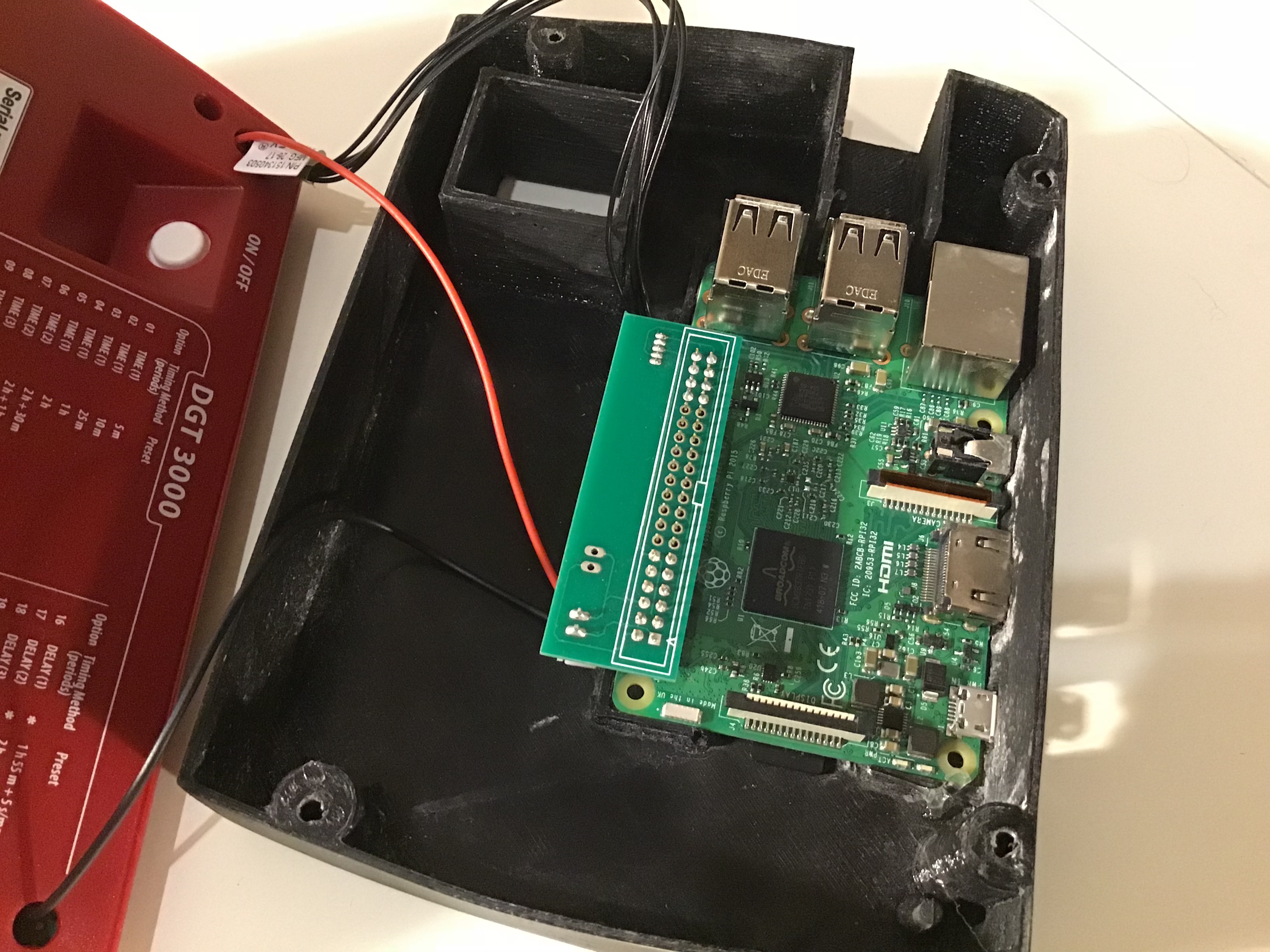
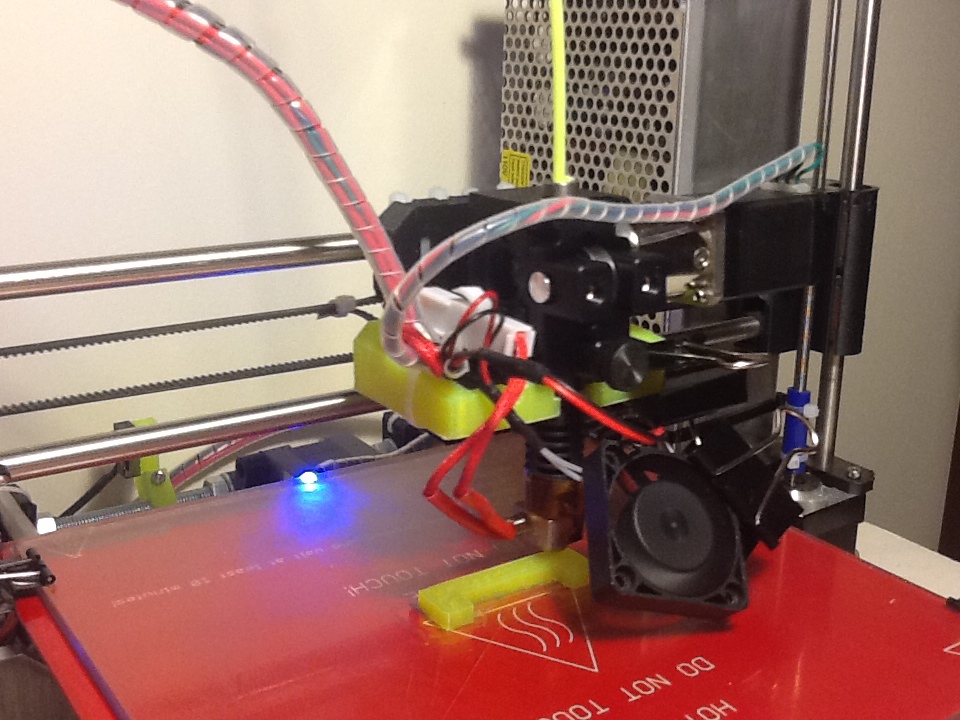
Based on the work others have done, I developed a board that allows you to connect a Raspberry Pi to the DGT-3000 without too much hassle. You need a soldering iron for the power cable (from the Pi to the DGT-3000).

IMG_8930

The solution consists of the following components:

  • A DGT-3000
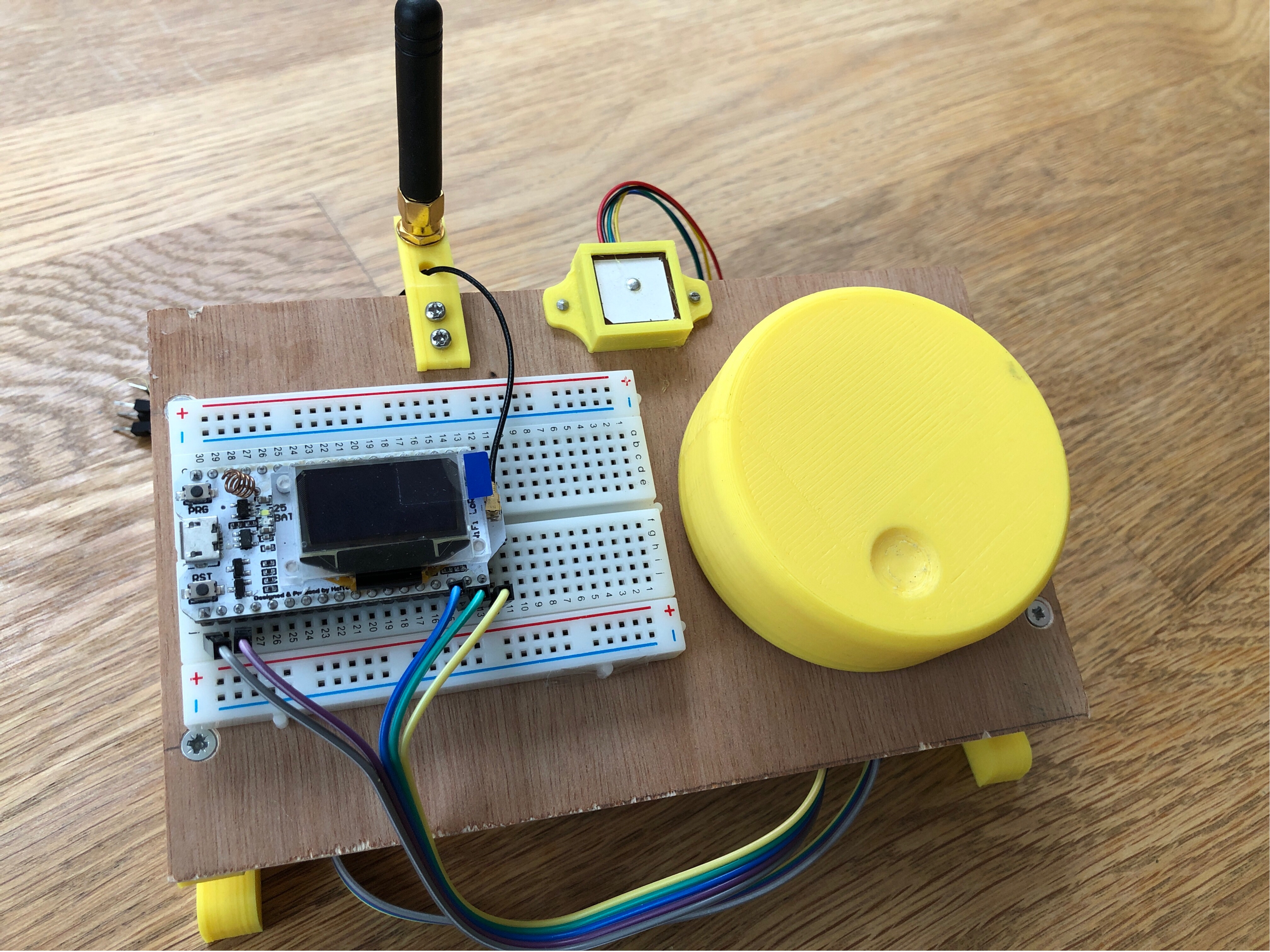
  • Raspberry Pi (a Raspi 3 will work best with the PicoChess engines, though a Zero W cor an older Pi can be used as well)
  • The connector cable (Pi-Hat with molex and power connector for the clock)
  • a 5-pin Molex connector cable
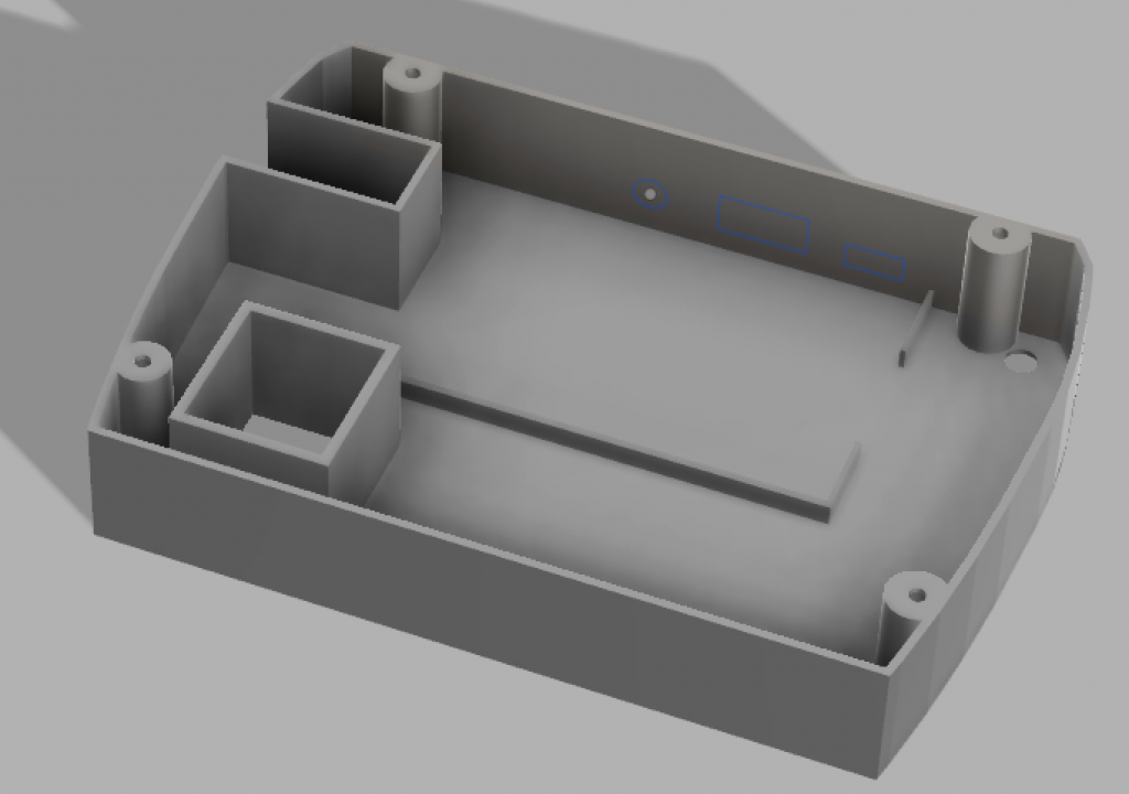
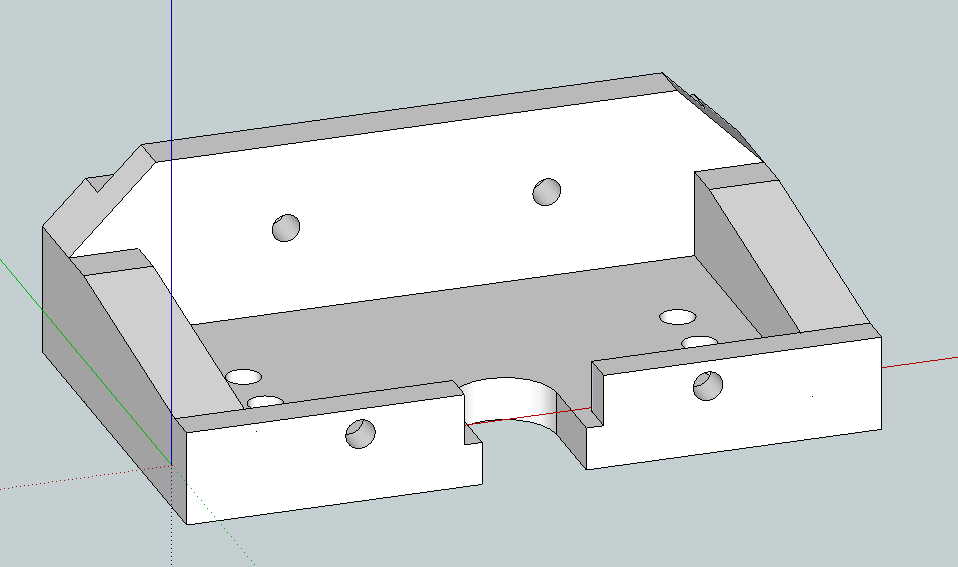
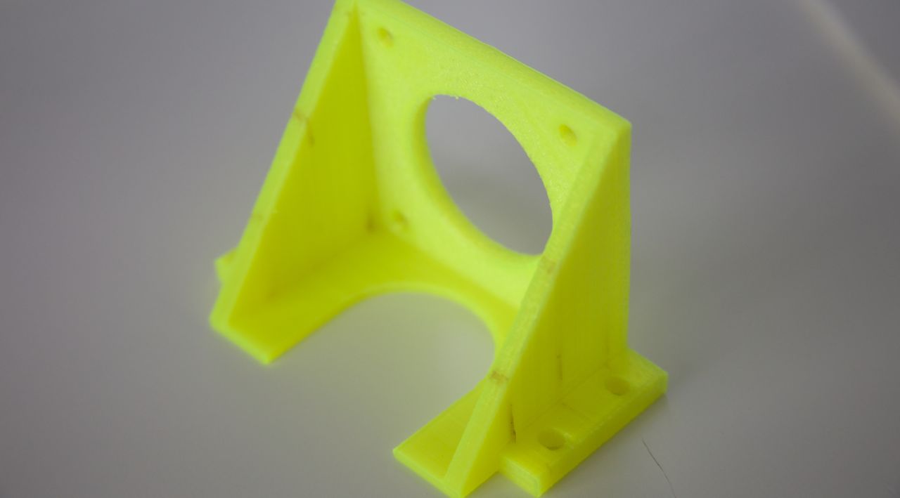
  • A Case that serves as a base for the clock and houses the Pi and the connector board

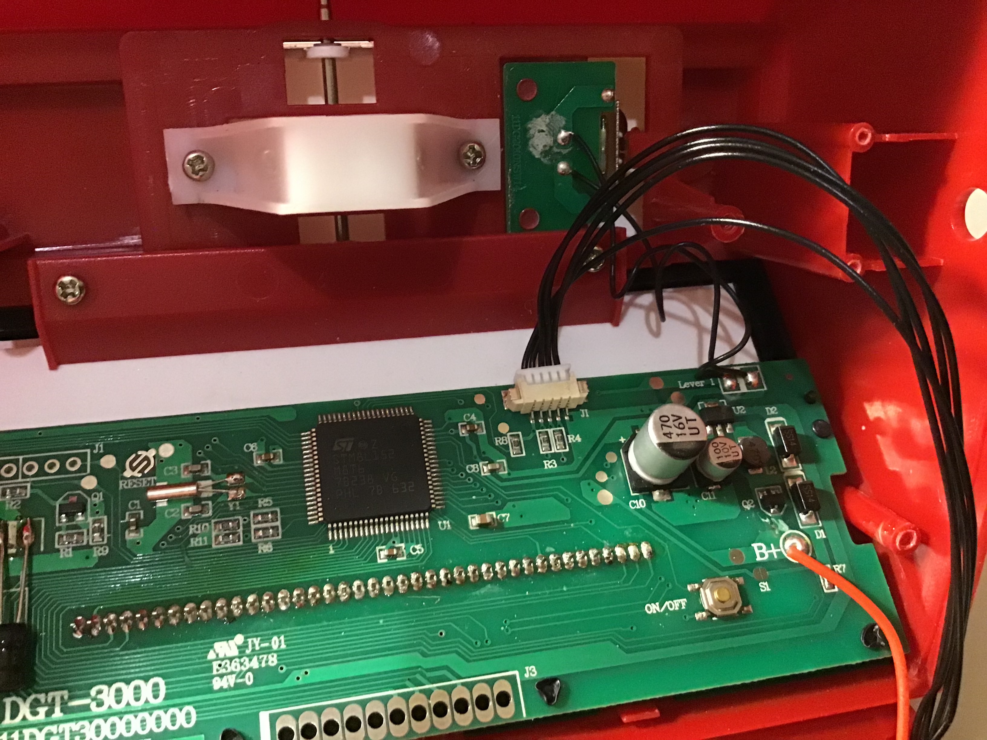
You remove the small board that holds the 3.5mm connector and instead the board will be connected directly to the RasPi via USB (I added a magnetic USB-C connector to easily hook up the board and the RasPi.
Just to clarify: After this conversion, you will no longer have the 3.5mm connector (and a little hole on the side of your DGt-3000).

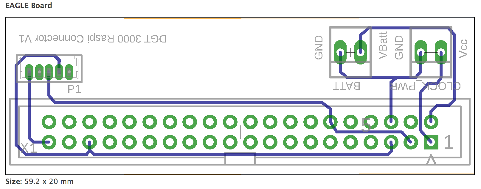
Layout of the molex connector:

DGT-3000 3.5mm to Molex Picoblade Small

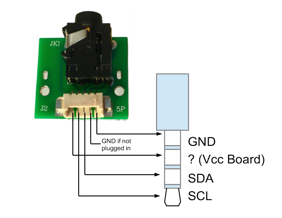
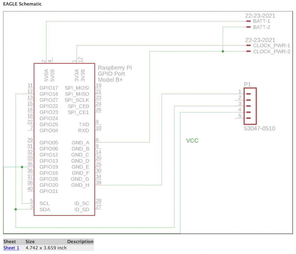
This is the layout of the board that connects the RasPi with the mainboard of the DGT-3000. The “Batt.” connector is optional. At some point I envisioned adding batteries to the case, but instead I just use a power bank to power the RasPi, which in turn powers the DGT-3000 clock and the DGT board (via USB).Screen Shot 2018-05-08 at 09.30.34 DGT-3000 Raspi Schematics Gerber Eagle Files


Case

In principle, you can mount the molex and battery connectors on either side of the board (rotate the connectors around the long side of the board, so they still connect to the same pads).

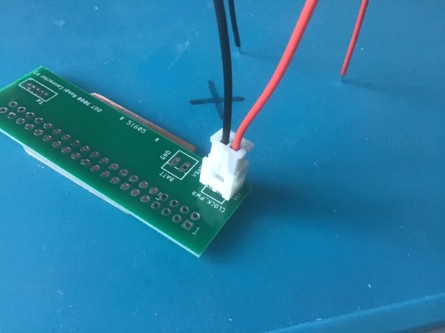
[5.Oct2019 correction:] The power cable that ships with the  connector set that I offer on eBay requires you to mount the connector the other way around (nudge facing the 40-pin connector, second picture below). As a rule, always ensure that the red cable (+) is the one closest to the corner of the board.
A big thank you to Simon for making me aware.

IMG_9567

Correct positioning of the connector/cable:

If someone manages to fit a rechargeable battery inside the case, please give me a shout:
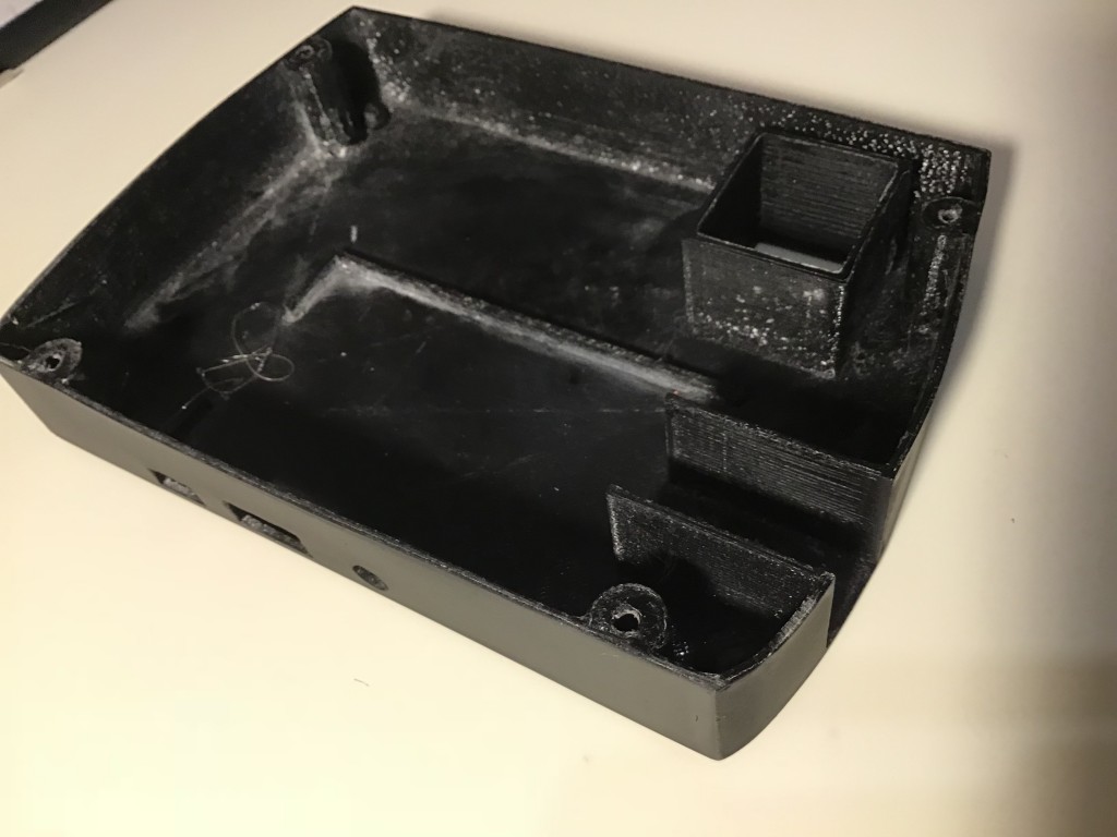
IMG_3988 IMG_9250 IMG_0946

Resources:

Description (RS-Components) Brand Distributor Part No. Price [£]
Molex PicoBlade 15134 Series Number Wire to Board Cable Assembly 1 Row, 5 Way 1 Row 5 Way, 300mm Molex RS Components  15134-0503 3.74
Molex PICOBLADE 53047, 1.25mm Pitch, 5 Way, 1 Row, Straight PCB Header, Through Hole Molex RS Components  53047-0510 0.4
250mm, 20 AWG, red, black
M2.2x20mm 304 Stainless Steel Phillips Countersunk Head Self Tapping Screw

I had a batch of the PCBs produced and am happy to sell them.
Search on eBay UK for DGT3000 PCB or the DGT3000 PicoChess Conversion Kit (Includes board, bottom case and cables. Not always available, contact me if you cannot find it).
Please note 75% of the proceeds go directly to Save the Cildren

Files: Eagle FilesDGT-3000 CaseGerberpicochess.ini

Wemos TTGO ESP8266 with 0.91 Inch OLED

Sites in China and eBay sell an ESP8266 module with 4MB flash and a build-in 0.91″ monochrome OLED display and a rechargeable battery port.

TTGO OTA Demo

Display

The display is a 128×32 pixel display connected via an SSD1306 controller.
It took me a while to figure out how to get the display to work – the Chinese sellers provide a rubbish demo script that uses the wrong pins for the I2C interface to the display controller.

The following pins and library combination works well:

U8g2 library: https://github.com/olikraus/u8g2
Data= pin 2
Clock= pin 14
Reset= pin 4

A demo program is available here: ESP8266_LCD_Demo

TTGO pinout

Drivers

As often, the board requires additional USB UART drivers.
I found suitable drivers for my Mac here – they also offer Windows and linux drivers:

https://www.silabs.com/products/development-tools/software/usb-to-uart-bridge-vcp-drivers

WiFi

The antenna gain seems to be quite poor – I noticed the module loses connection to my AP about at half the distance that my ESP8266-12 or ESP8266-01 modules tolerate.
I successfully managed to run OTA updatable code (see example).

 Layout

The board layout is a bit unfortunate as so far as the micro USB connector is mounted on the top, protruding in height above the display, which will not allow to mount the module flush against the top of a case.

Two buttons (reset and GPIO01) allow to invoke flash mode and reset the device, which comes in handy during development.

The pins are labelled both on the front and back side of the board.

TTGO frontTTGO back

Price

At time of writing, the board can be bought between $9 and $12 from Chinese sellers and for $15-$20 from Western distributors. The ones I bought came with a plastic box, a battery cable and connector and pin headers (not soldered)


Arduino Nano Eagle Library

This is based on Warren Brayshaw’s post here, which seems to have the A0-A7 lines reversed (compared with the Nano V3 . Maybe it once was correct for an earlier version of the Nano – I don’t know). The library below has been updated to be consistent with V3. The ICSP headers are not included, just the headers on the long sides of the nano board.Arduino_Nano_library


Download: CRE-Lib1.lbr

Micron 3DP Metal Extruder

Adding an all-metal extruder to a Prusa i3.

The Wade extruder on my i3 started to slip and not enough filament was extruded, so the prints started to look flakier and flakier. I checked the extruder, refurbished the hobbled bolt, but the problem came quickly back. Only once I increased temperature to over 230C (for PLA!) it completed prints – of course the result looked like roasted marshmallows.

So I ordered a new J-Head hot end (0.4mm) and a new all-metal extruder. Price on ebay was $175 plus $20 shipping. Quite steep, but I have no regrets! Build quality is excellent and the Nema 11 stepper has plenty of power thanks to the gearbox (at first, I used same driver setting as for my Wade extruder’s Nema 17 and subsequently the stepper would become very hot. Adjusting the reference voltage of the driver board to 0.45V solved the problem).

I had to print a new mount to fit the extruder. That was a bit of a challenge, given I own only one 3D printer, and that one was broken. I managed to get one decent print: enough to mount hold the new extruder in place. Once I had the printer re-adjusted (M92 X80.00 Y80.00 Z4000.00 E1333.33), the first task was to print a better mount.

Result is attached below.

Metal Extruder
Metal Extruder


Not sure if it’s the new extruder or the recalibration of the machine (incl. resetting x and z end stops), but now I am finally able to print straight onto glass (using a watered down PVA solution to improve stickyness).

Details for the mount are attached. I had to move the extruder a bit further out, so the Nema 11 motor would not crash into the right Z-thread.

Printing a fan mount is next. The extruder has two M3 holes at the front, that can be used to attach a fan (surely they were put there for something else, but they work just fine).

Screen Shot 2014-06-19 at 23.13.48


Metal extruder mount details (for prusa i3):

STL file: metal extruder mount (repaired).stl
Sketchup file:metal extruder mount.skp

Marlin configuration file (RAMPS 1.4): Marlin 1.0 config (EEPROM)

3D printed Nema 23 mount

Print you own Nema 23 motor mount. A low cost alternative to aluminium mounts and more accurate than most wooden constructions.

Nema motor mounts are usually quite expensive. The quality of the mount does very little to a CNC machine’s accuracy. So I decided to print one. It raises the motor about 2mm above ground. My motors fit snug into the mount hole.

Screen Shot 2014-03-26 at 22.41.04

The mount is relatively sturdy. I had a bit trouble with warping, since my heated bed didn’t work properly. Thickness of the base can be increased to improve rigidness. For the particular machine I built, 2 mm was al I could afford.

Nema23-Mount.skp
Nema23Mount.stl