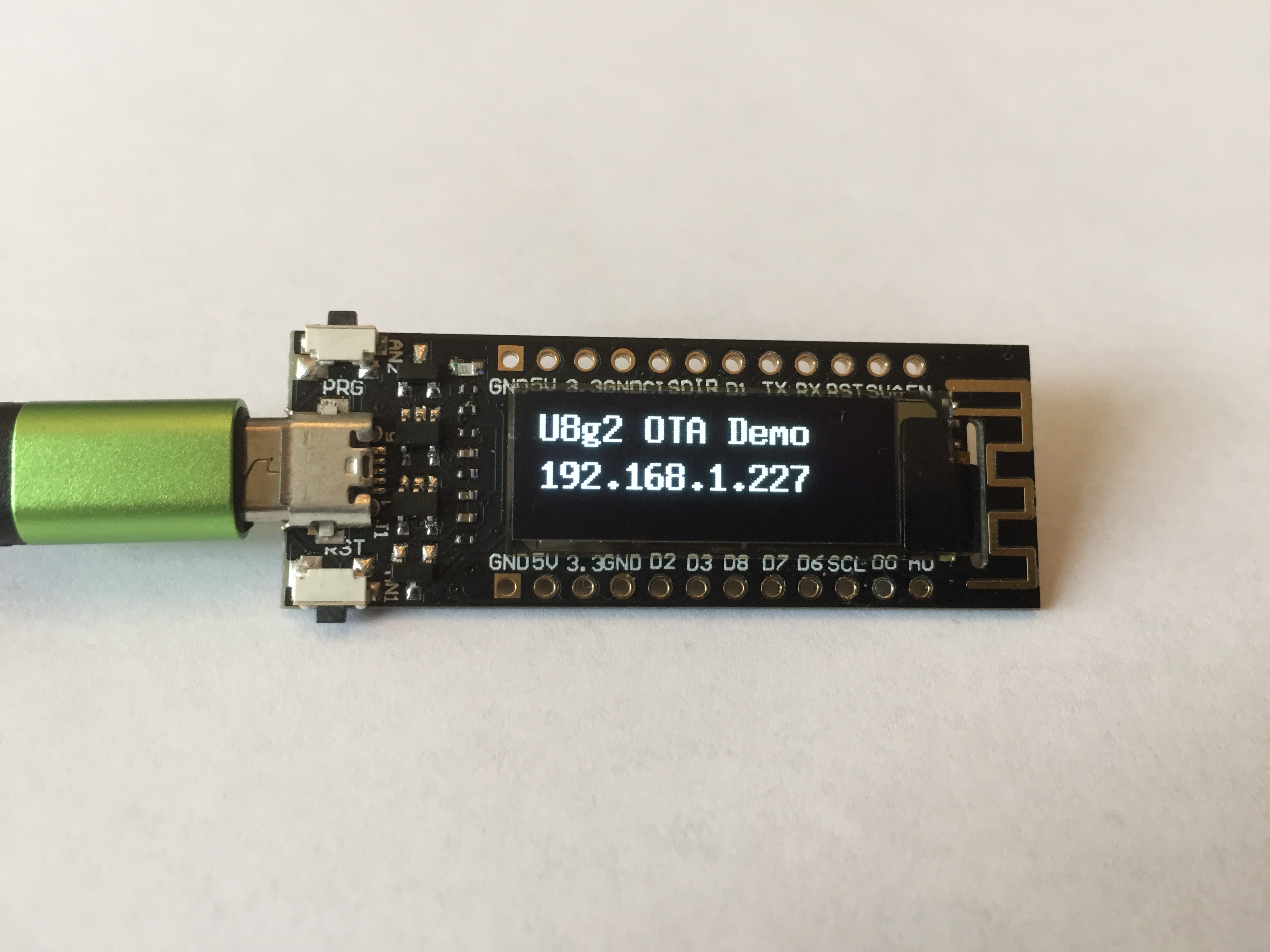
Sites in China and eBay sell an ESP8266 module with 4MB flash and a build-in 0.91″ monochrome OLED display and a rechargeable battery port.
Display
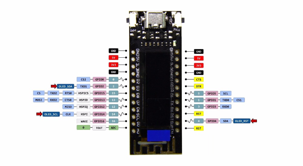
The display is a 128×32 pixel display connected via an SSD1306 controller.
It took me a while to figure out how to get the display to work – the Chinese sellers provide a rubbish demo script that uses the wrong pins for the I2C interface to the display controller.
The following pins and library combination works well:
U8g2 library: https://github.com/olikraus/u8g2
Data= pin 2
Clock= pin 14
Reset= pin 4
A demo program is available here: ESP8266_LCD_Demo
Drivers
As often, the board requires additional USB UART drivers.
I found suitable drivers for my Mac here – they also offer Windows and linux drivers:
https://www.silabs.com/products/development-tools/software/usb-to-uart-bridge-vcp-drivers
WiFi
The antenna gain seems to be quite poor – I noticed the module loses connection to my AP about at half the distance that my ESP8266-12 or ESP8266-01 modules tolerate.
I successfully managed to run OTA updatable code (see example).
Layout
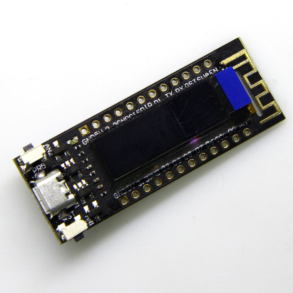
The board layout is a bit unfortunate as so far as the micro USB connector is mounted on the top, protruding in height above the display, which will not allow to mount the module flush against the top of a case.
Two buttons (reset and GPIO01) allow to invoke flash mode and reset the device, which comes in handy during development.
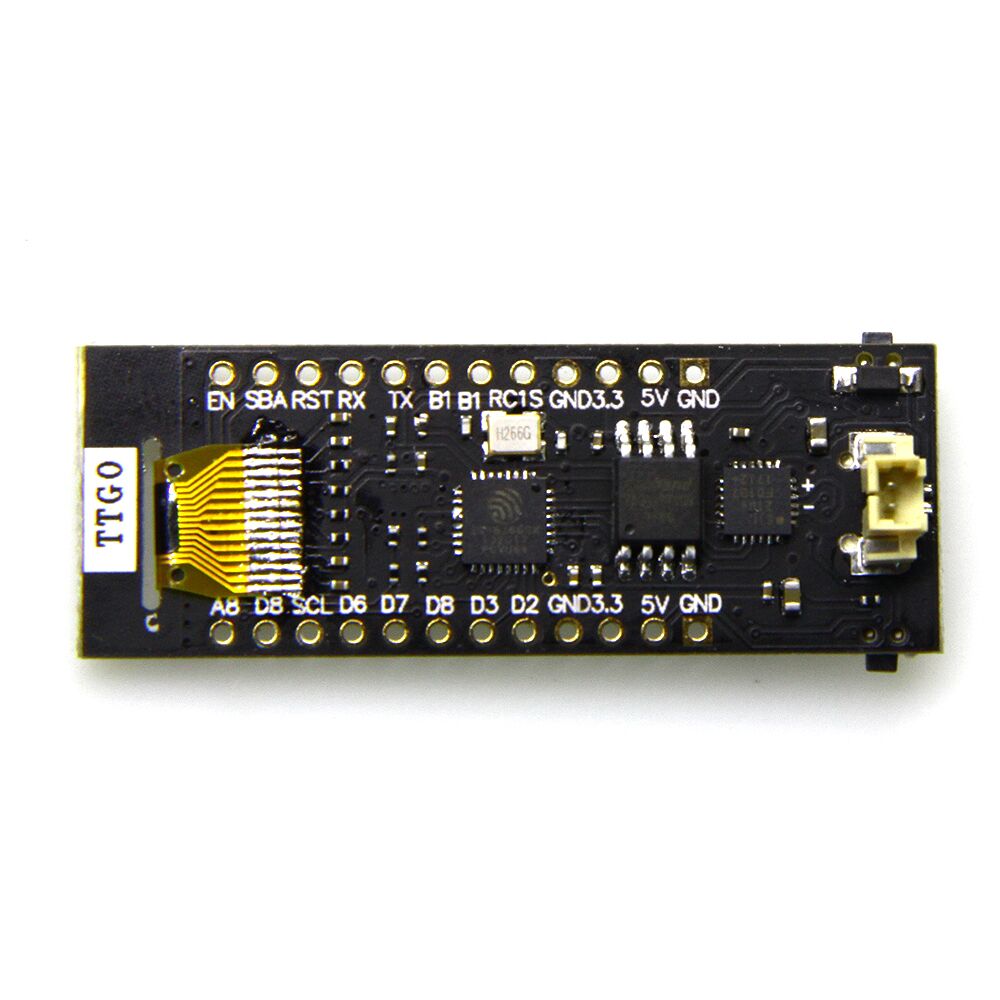
The pins are labelled both on the front and back side of the board.
Price
At time of writing, the board can be bought between $9 and $12 from Chinese sellers and for $15-$20 from Western distributors. The ones I bought came with a plastic box, a battery cable and connector and pin headers (not soldered)
How should i do if i’d like to use it with adafruits SSD1206 library?
AFAIK, the adafruit library has a config.h (or similar name) file somewhere in a subfolder and there you need to make sure resolution is correct. You also need to call the correct constructor. No experience with that LCD/library combination.
This example of the Adafruit_SSD1306 library worked for me.
I only modified initialising Wire with the appropriate I2C pins.
...

#define OLED_SDA  2

#define OLED_SCL 14

#define OLED_RST  4

...

 Wire.begin( OLED_SDA, OLED_SCL);

...
Code available here
(Sorry if I double posted. My first comment did not show up. Maybe because it contained some code)
I just got a couple of these in the mail and they seem to work fine. But I have two problems that I haven’t solved yet:
1. They will not start the code when you connect power. I need to push the reset button to get the code going.
2. I don’t manage to address the second button. I want to be able to use it to trigger some code.
Do you by any chance know how to fix these issues?
The only thing I do know about the PRG button is that one pin is connected to GPIO3.
The other pin however is a mystery.
1. same for me , unless you wait a long time without power (more than 5 min ,i think ; not measure)
i dont understand why ; someone do ? (maybe due to u8g2 , not yet tested other )
2.PRG button : one side (near “G” is connected to “D3” (GPIO0 ) ; the other side is not connected (missing ?)
it is possible to connect it ( near “P” )on the ground of usb connector ( or other gnd ,if you want)
i think there is some mistake on the schematic GPIO 0,2,4 are not good
D2 is GPIO4 D3 is GPIO0 SBA is GPIO2 (D4)
and “EN” on the bord is well EN , not a second RST in yellow
tell me if i am wrong….
the problem is coming from high voltage (7v) that remain on pin 14 of oled display , but why ?
if you discharge the cap on pin14 , the esp8266 boot normaly
i will continue investigation later ……..
Interface Pin Function of oled (WEO012832 ?? )
No. Symbol Function
1 C2P
Positive Terminal of the Flying Inverting Capacitorr Negative Terminal of the
Flying Boost Capacitor The charge-pump capacitors are required between
the terminals. They must be floated when the converter is not used.
2 C2N
3 C1P
4 C1N
5 VBAT
Power Supply for DC/DC Converter Circuit
This is the power supply pin for the internal buffer of the DC/DC voltage
converter. It must be connected to external source when the converter is
used. It should be connected to VDD when the converter is not used.
6 NC No connection
7 VSS
Ground of Logic Circuit
This is a ground pin. It acts as a reference for the logic pins. It must be
connected to external ground.
8 VDD
Power Supply for Logic
This is a voltage supply pin. It must be connected to external source.
9 RES#
Power Reset for Controller and Driver
This pin is reset signal input. When the pin is low, initialization of the chip is
executed.
10 SCL I2C mode is selected, D2, D1 should be tied together and serve as SDAout,
SDAin in application and D0 is the serial clock input, SCL.
11 SDA
12 IREF
Current Reference for Brightness Adjustment
This pin is segment current reference pin. A resistor should be connected
between this pin and VSS. Set the current lower than 12.5μA.
13 VCOMH
Voltage Output High Level for COM Signal
This pin is the input pin for the voltage output high level for COM signals. A
capacitor should be connected between this pin and VSS.
14 VCC
Power Supply for OEL Panel
This is the most positive voltage supply pin of the chip. A stabilization
capacitor should be connected between this pin and VSS when the converter
is used. It must be connected to external source when the converter is not
used.
I just buzzed out the board and SBA is connected to the SDA pin on the OLED module.
I think SBA(SDA?) is GPIO4 D2
why , but why , is there a 390k between 3.3v and Vdd of oled ????????????
replace this resistor with a simple wire , and the boot problem is solved !!!!!!
on the back side of print , above “D6” there is two caps and the following componant is the 390k resistor
Anyone tried running Tasmota on this board? I loaded it on, set the i2c pins, and then i2cscan finds the oled address.
however after power cycling it, it no longer finds the i2c address.